Options

General

Fig 1. - PCB-Investigator Options Dialog - Tab: General
  • Working Directory: Directory zip files get extracted as well as the internal ODB++. It is saved if you import a different data format like Gerber or GenCAD. Via the buttons working directory can be changed and set back to the default value.
  • Ini File Location: Location of the ini file containing your current settings. A common use case e.g.: You want to change computers, but take all of your settings with you, so you simply copy the ini file and paste it into the ini directory of the new computer.
  • CSV separator: CSV files are usually separated by comma, but in some languages, e. g. german, the default separator is a semicolon. The CSV Separator option allows you to freely change the default separator of all the many list exports throughout PCB-Investigator at any given time.
  • Center/Position Zoom: By default the zoom centers on the current mouse position and shifts the representation accordingly. Deactivating this option, it zooms on the center of the screen often leading to your board leaving the visible area. That´s why deactivating is not recommended.

Display

Fig 2. - PCB-Investigator Options Dialog - Tab: Display
  • Real time drawing: If the view changes (e.g. because you pan or zoom), the visualisation gets drawn anew. Changing the view again while the previous drawing process still hasn't been completed, usually does not cancel the previous drawing process. Activating the option "real time drawing" changes this default setting and forces all drawing processes to be aborted allowing only the current view to be drawn, which may improve performance, but can cause jittering.
  • Max visible layers: Limits the maximum number of layers you can activate in your layer stack up. If the number of active layers would be exceeded, the most recently activated layer gets turned off.
  • Show Tool Tip: If this option is deactivated, no tool tips are shown when hovering over objects in the visualisation.
  • Zoom selection distance: Offset that is added to your current mouse position while zooming.
  • Layer list:
    • Use large item style: displays the step items in a bigger style.
    • Use dynamic item height: make the height of the step items dynamic.

Panel

Fig 3. - PCB-Investigator Options Dialog - Tab: Panel
  • Panel Info: Determines, whether the contour (outline of the whole board) gets drawn or not. This setting corresponds with view »
  • Flatten: Switch between drawing all or only the the first part of a panel in the panel view to improve performance. This setting corresponds with Edit »
  • Use Advanced Transform DLG: Shows advanced options in the transform dialog (edit » transform dialog) if activated.
  • Flatten Step Options: Large designs often require long render times, the Flatten Step Option allows you to select a performance optimised method provided that your system is powerful enough.
    • Standard: for systems with less than 10GB RAM
    • Standard: for systems with more than 10GB RAM

Grid

Fig 4. - PCB-Investigator Options Dialog - Tab: Grid

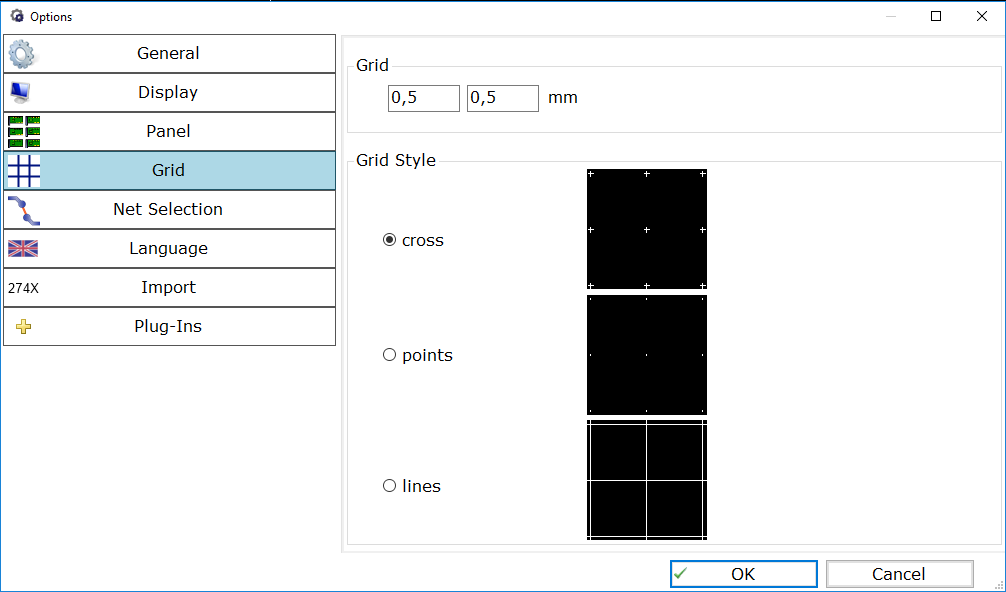
The Grid tab allows you to fully customise your Grid choosing from crosses, points and lines and adjusting the width and height of a cell. Please note that if you want to see the grid, you have to switch it on first via View » . The grid defined here is also used, if you activate the Snap to Grid option in the Add dialog.


Net Selection

Fig 5. - PCB-Investigator Options Dialog - Tab: Net Selection

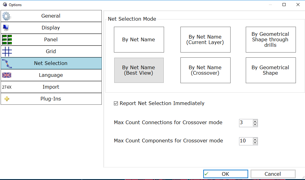
The Net Selection tab allows you to select one of six possible options to select a net with, an option you can also find under start » Select Net for quick access, as well as the customisation options for the Crossover selection method.

  • The Crossover method options allows you to state the maximum number of nets that can be skipped. For more information please refer to Mouse Tools » Net Mode: Crossover
  • Report Net Selection Immediately: Instant colour highlighting of selected elements in the CMPs and Nets tab of the information area in the bottom left corner of PCB-Investigator.

Language

Fig 6. - PCB-Investigator Options Dialog - Tab: Language

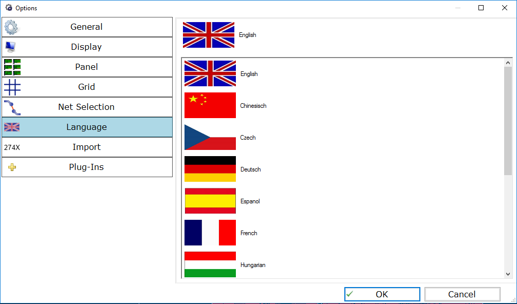
The language tab allows you to select a different language for all of PCB-Investigators menus, tool tips, etc. Please note, not all translations are equally complete and accurate. If a text has no equivalent in the selected language, it defaults to english. If you have the necessary writing permissions you may also edit the translation files directly, which by default can be found in: "C:\Program Files (x86)\easylogix\PCB-Investigator-Demo\language_package" as CSV files (please note that the CSV language files may be overwritten while performing an update so make sure you have a copy of your customised files outside of the easylogix folder).

Import

Fig 7. - PCB-Investigator Options Dialog - Tab: Import


  • File formats like for example Gerber and Excellon usually have a definition in their headers containing the used unit and number format, which are necessary for the file information to be correctly read. In some cases this essential header is missing and therefore gets replaced with a default setting. Since this default setting can differ from company to company you can customise it here.
    This option is also relevant when importing data via drag & drop, since in contrast to using the import menu there is no option allowing you to change these interpretation data normally found in the file header.
  • Options for Polygonizing Objects: Allows you to set the length of the lines used to draw arcs.
  • Use highest Component File: Some programs save memory files with former states adding a constantly increasing number to the default file name of "components", where the highest number corresponds to the most recent version. Deactivating this option tells PCB-Investigator to always use the standard "components" file without numbers.
  • Route Option: The .comp attribute defined in the ODB++ specification is applied to all elements containing one of the three attributes (none, left, and right). The Route Options allow you to select, how PCB-Investigator should respond to it.


Plug-ins

Fig 8. - PCB-Investigator Options Dialog - Tab: Plug-ins
  • Plug-in path: The path to the plugins that you created yourself.
  • Proxy for Web Connection: If you are behind a company firewall and only have restricted internet access, you have to configure the company proxy here to enable PCB-Investigator to get the needed connection.
  • Direct 3D Plug-in: If your graphic card has no 3D capabilities, an error would be thrown. To prevent this from occurring constantly you can deactivate 3D capabilities with this option.
  • Enable Debug Output: To get more comprehensive error descriptions in the "Error-Log" tab of the information panel in the left bottom corner of PCB-Investigator, you can activate this option.