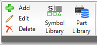
Clicking on “Add” that can be found under Fabrication, the following window will open.

You have the possibility to add 5 different types of objects:
1. Line
2. Pad
3. Surface
4. Arc
5. Text.
The here mentioned objects correspond to the different types of objects ODB++ provides.
The description of the placement of lines forms the basis for the explanation of the addition of all the other objects. Overlapping configuration options will only be described here.
1. Line

1. At first, you have to choose the layer on which you want to add a line.
2. If you want to add attributes to the line, you have to set a hook next to “attributes” and then click on values. Another window will open, which allows you to choose the propriate attributes.

After you have chosen the propriate attribute, click on “Add or Overwrite”. To add the selected attributes, click on “Accept”.
3. You can also decide, whether you want to add a positive or negative line (polarity). If you would put a negative line above a positive on, the negative line would cut away the overlapping parts of the lines.
4. There are three more options you can choose from:
5. To select the type of line you want to add, you have to click on “Symbol” or you have the option to pick a line that’s on the currently opened design. Clicking on “Symbol” will open up another dialog, the Symbol Library. You can then select the propriate line from the symbols provided there. For more information on how to work with the Symbol Library, move to “Symbol Library”.
6. If you choose the other option “Pick”, your mouse will turn into a pen allowing you to pick the type of line on the graphic interface you select for adding.
How to add a line: After the selection of the symbol type, you can now add the line. To do so, right-click on the position in your design that you chose for the new line. A double-click will end the line.
7. You also have three more different options when it comes to adding lines:
8. You are also able to place lines by entering the X and Y coordinates of the start and end point. “Add” will then place the line.
2. Pad
If you want to add pads, click on the button "Pad". You will then see the following window.

The adding of pads works analogous to the adding lines.
There are only a few different options that have to be additionally explained.
You can choose whether to mirror the pads to be placed by setting a hook on either “no Mirror” or “Mirror”.
Another option is the configuration of the angle (0°, 90°, 180°, 270°) that shall be used when placing the pad.
3. Surface
If you want to add a surface, click on the button "Surface". You will then see the following window.

When adding surfaces, there are also a few options differing from the addition of lines. These shall also be explained here.
If you want to add a surface, you have three options:
Polygon
You can either place a polygon by entering the X and Y coordinates. Enter the coordinates and click “Start”. The defined point will be the starting point of your polygon. Enter new coordinates and click “Add Point”. You can then continue with this procedure until you want to close your polygon. To do so, click “close”.
The other option for placing polygons is just to do a simple right-click at the propriate position in the design. Continue to place more angles of the polygon by further right-clicks. A double-click will automatically close the polygon.
If you place an angle in a way that will hinder the automatic closure, the new (wrong) line will be shown as red instead of blue.
Besides the polarity, you can also select whether to place an isle or a hole into an existing surface. It`s not possible that holes cut each other.
Rectangle
To add a rectangle, you can either also use the method of entering X and Y coordinates or you can select the starting point of your rectangle by a simple right-click. The size of the rectangle can then be determined by moving the mouse. Double-clicking will place the rectangle.
Like when defining the polygon, you have the same two options: You can also select the polarity and whether to place an isle or a hole into an existing surface.
Flood Layer

To flood a layer, you have to adjust some parameters to configure the distances that shall be held and the minimal area (regarding the min. total area) and size of the flooding (regarding the min. length /width):
In the case of “Flood Layer”, the use of entering X and Y coordinates is not reasonable.
4. Arc
If you want to add an arc, click on the button "Surface". You will then see the following window.

When adding arcs, there are also a few new options that haven´t been explained yet.
Firstly, you have to define the diameter. You can either define it by entering a specific value or you use the pick tool (“Pick Diameter”) to choose a propriate diameter that has already been used in the graphic interface.
When placing the arc, there are three different methods for setting it:
You can also decide for the direction when placing the arc. You can either choose to place it clockwise or counter clockwise.
5. Text
If you want to add a text, switch to the button "Text". You will then see the following window.

To place a text, you can decide for the polarity (positive, negative), if you want to mirror the text (mirror, no mirror) and the angle of placement (0°, 90°, 180°, 270°).
You can either place the text by entering values for the X and Y location or you can place it by double-clicking on the propriate position on your design in the graphic interface.
The “X-Size” and “Y-Size” refer to the width and length of the letters.
A simple right-click adds the text on your design in the graphic interfact. You can still place the text on another position by simply moving your mouse. A double-click will then place the text.