 |
Stencil Preperation helps to create stencil with openings for each paste depot. |
Note: For high quality, it is recommended not to cut pin pads. You can combine areas e.g. from different parts to get ideal areas.
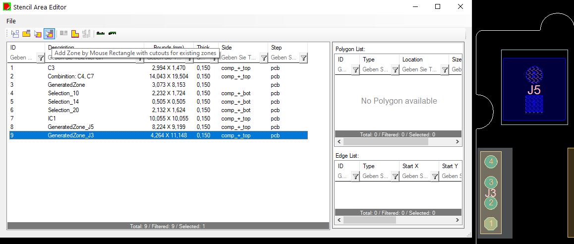
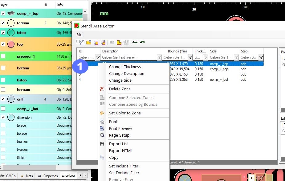
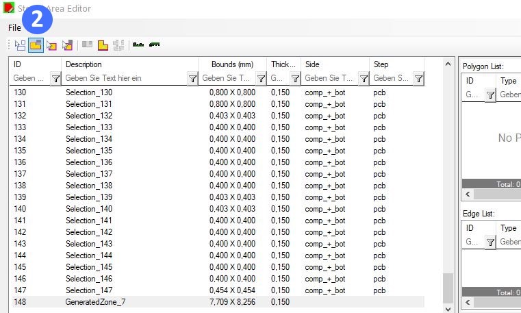
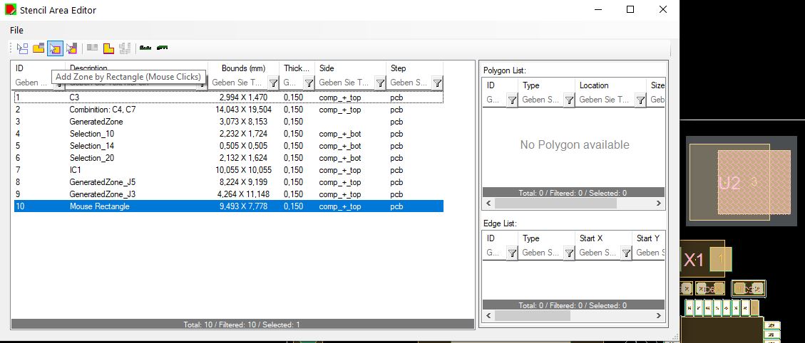
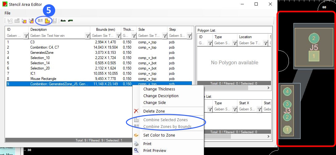 Combine different zones to one zone
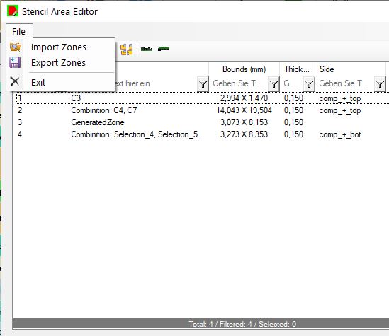
-->Zone settings can be saved in ODB attributes, exported as xml and imported from xml.
The Stencil Generator uses all zones defined by the Stencil Area Editor. If there are no zones the outline will be used as main zone. Use default rules for your company. Setting a package group, enables the Wizard to set the rules regarding it. SOICs, Chips, BGAs and any definition needed. The Wizard is delivered with predefined settings. To adjust all data preparation to your product you can setup own data preparation Scripts to adjust to your equipment.
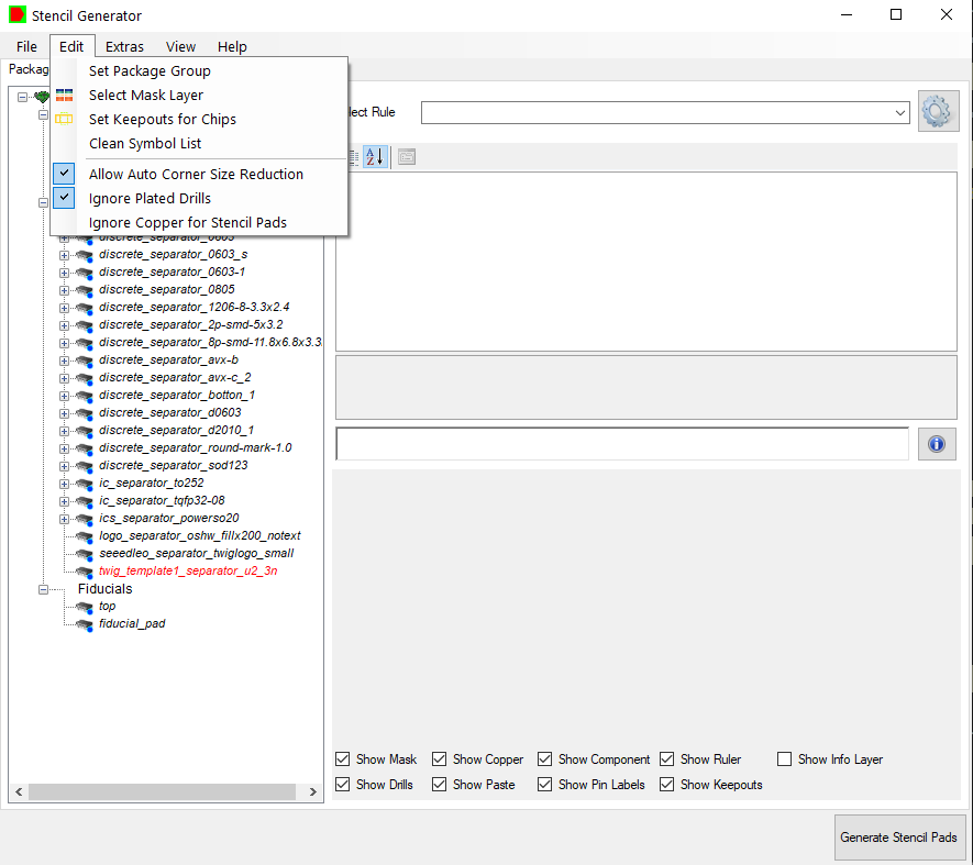
Set Package Group is only necessary if your data don’t contain a proper information. Customers with EPL (“Easylogix Part Library”) can resolve trusted data from EPL. The Wizard also process layouts with multiple mask layers in the stack-up. Set “Keepouts for Chips” is only available if you have MPN packaged defined. It will handle the usable area for you. You also can set plugged drills as free usable area.
You have the possibility to set rules by package, set extra rules for components in defines zones or to set a rule for each component.
To set another rule to your component, select one in the given list.
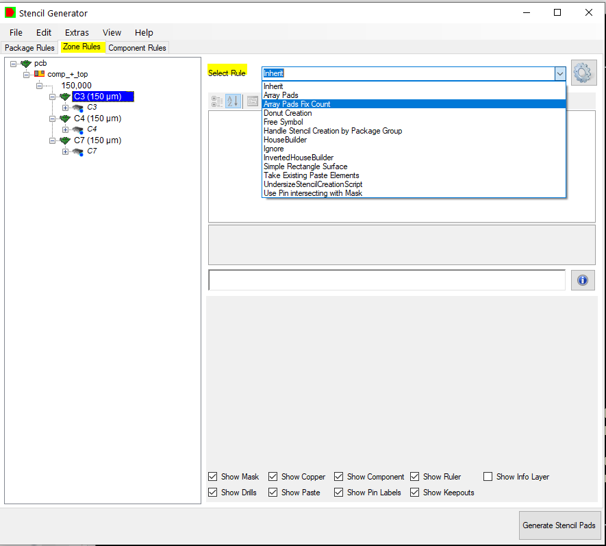
You can add your own rules by clicking on the setting symbol.
Send the stencil data in your preferred format to your supplier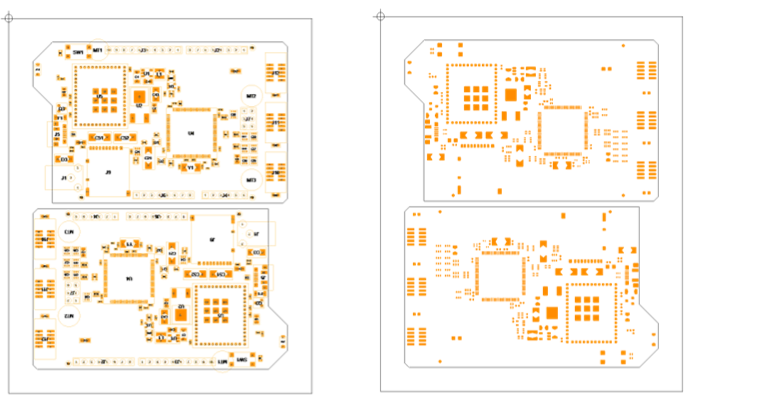 |
Result of the rule-base stencil wizard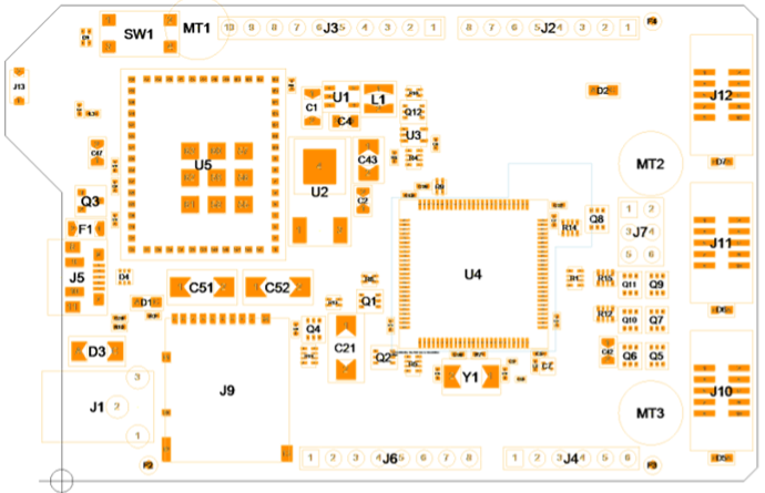 |
Before and after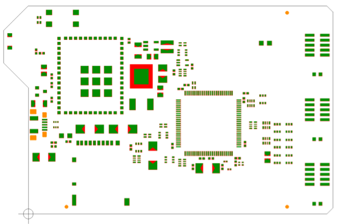 |
Stencil pad details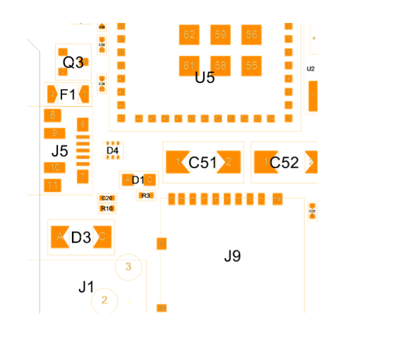 |
Here is a short video to show special cases in one of our demo designs:
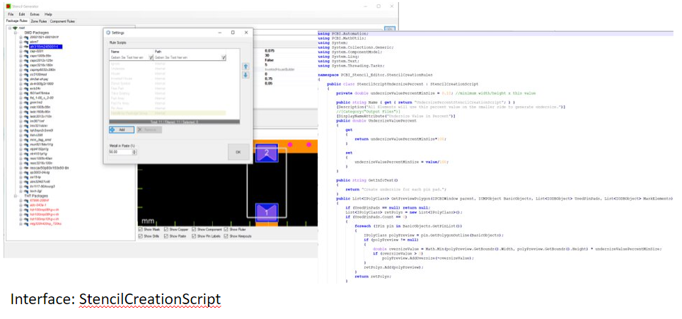
To automate your custom stencil scripts, it is necessary to use the StencilCreationScript interface.
Here is a link to see all details for your implemention manual.
You have to set public porperties to give user options to change in the property grid, there is also a method to create the preview and the pads. You should fill the corde with all calculation you need e.g.
public bool CreatePads(IPCBIWindow parent, IStep step, IODBLayer StencilLayerOutput, InterfaceCMPObject BasicObjects, List<IPolyClass> UsedPinPads, List<IPolyClass> MaskForCheck, List<IPolyClass> Drills, double ThicknessPaste)
{
if (StencilLayerOutput == null || BasicObjects == null || UsedPinPads.Count == 0)
return false;
bool IntersectWithMask = false;
CreateRectangleElement(StencilLayerOutput, UsedPinPads, MaskForCheck, Drills, BasicObjects, out IntersectWithMask);
return true;
}

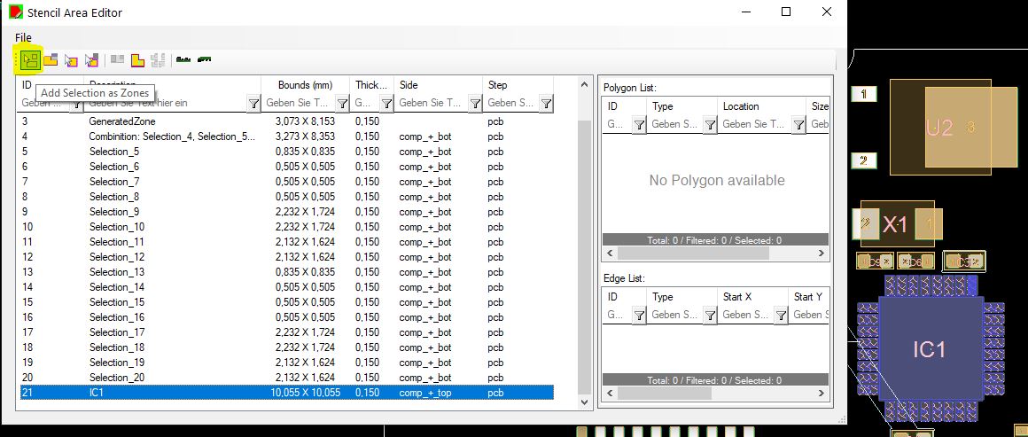
In the options area (1) you can add your custom developed scripts (2).
This rule specifically addresses the process of creating stencils for different package groups, each with its unique characteristics and requirements. It is important to have the PACKAGE_GROUP property!
You can import an library to get the PACKAGE_GROUP Property or let PCB-Investigator create them for standard definitions (check the Edit menu => Set Package Group)

Note: this rule is the most powerfull rule and handle all types of packages with good pad creation rules, we recommend to use this ad default and handle only special packages with extra rules!
The StencilScriptUndersize class defines the necessary parameters to create a similar structure around a stencil pad for solder paste applications with smaller size. It is used for automating stencil generation and includes geometry, shape characteristics, and spacing considerations.
| Property | Type | Description |
|---|---|---|
Undersize Value in Percent |
double | All Elements will use this percent value on the smaller side to generate undersize. |
Undersize Value in MM |
double | All Elements will use this value in mm to generate undersize. |
Corner Radius (MM) |
double | Corner radius for rounded elements in MM. The value is independent of the undersize and can change the earthings with different values. |
Max Size of one Element (MM) |
double | Each element has maximum width and height, if the size is bigger it is automatically splitted in more elements. Value is in MM. |
Steg for Big Elements (MM) |
double | If the element is bigger MaxElementSize it use this value to split the size in more elements. Value is in MM. |
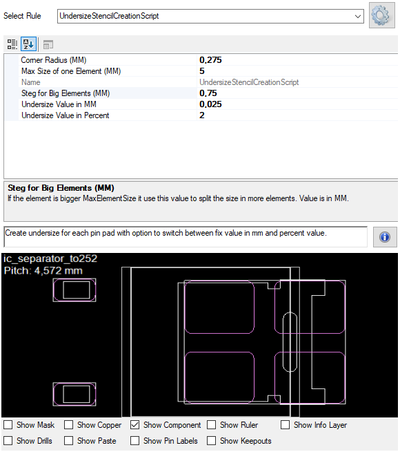
These parameters help define the geometric and contextual constraints for automatically generating stencil pad protection using a smaller-shaped perimeter.
Note: If the undersize values to small no pad will be created, the rule checks the mask layer for intersecting!
In stencil design, a donut shape is used to define a circular opening with a central void (hole), commonly used for thermal reliefs or annular ring designs. The donut is generated around a pad center based on several configurable parameters.
| Property | Type | Description |
|---|---|---|
InnerDiameter |
double | Defines the inner diameter of the donut. This is the size of the central hole that will not be cut into the stencil. |
OuterDiameter |
double | Specifies the outer diameter of the donut, representing the total size of the stencil opening. |
AngleStep |
double | Angle between each arc segment when constructing the donut shape. A smaller step creates a smoother circle. |
OffsetX |
double | Offset in X-direction from the pad center, applied to reposition the donut shape. |
OffsetY |
double | Offset in Y-direction from the pad center. |
Rotation |
double | Applies a rotation (in degrees) to the donut shape around the pad center. |
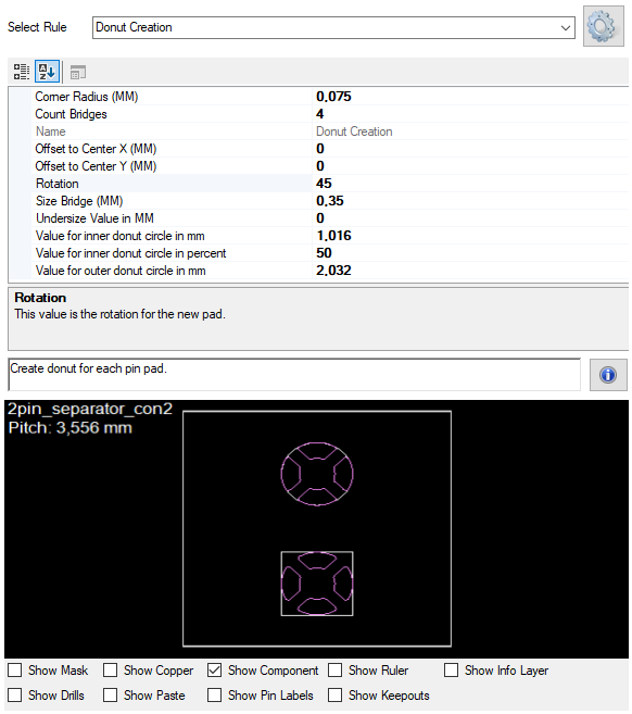
These properties are used by the StencilScriptDonut class to calculate and render the donut shape on stencil pads. The donut is typically composed of an outer arc (outer diameter) and an inner arc (inner diameter), combined with connecting lines to form a closed shape.
Ensure that InnerDiameter is less than OuterDiameter to create a valid donut. Adjust AngleStep based on performance vs. accuracy needs.
Array creation is used to replicate pad openings in a structured pattern. This is especially useful for components like QFP or QFNs,
where cooling pads are very big and replaced by array formation. The array is defined using specific rules and transformation parameters, it gives you an easy way to define an array of similar (rounded) rectangles.
| Property | Type | Description |
|---|---|---|
Array Field Count in X direction |
int | Fix Array Rule only: Array pads count in X direction. |
Array Field Count in Y direction |
int | Fix Array Rule only: Array pads count in Y direction. |
Corner Radius (MM) |
double | Corner radius for rounded elements in MM. |
Utilization Array Area (%) |
double | Utilization of avalable area in percent (only used if no fix size is used and value >0). This option will ignore the undersize value and depending to the settings it is possible the values are not exact. |
Minimum Array Field Size (MM) |
double | Array pads has minimum this size, if there is only space for one pad no array created. |
Offset to Center in X direction (MM) |
double | Fix Array Rule only: X offset to shift the array from the pad center. |
Offset to Center in Y direction (MM) |
double | Fix Array Rule only: Move array in Y direction from center of the pin. |
Distance Array Fields (MM) |
double | Array pads has this distance to next pads. |
Undersize Value in MM |
double | This value is only used if no Array size is defined. All other Elements will use this value in mm to generate undersize. |
Ignore Mask Intersecting |
bool | Do not check for mask intersecting (add all array elements without checking mask). |
Array Size Width (MM) |
double | Width for complete array, if it is =0 the original element width is used. |
Array Size Height (MM) |
double | Height for complete array, if it is =0 the original element height is used. |

These properties are used in the StencilScriptArray class to define how shapes are duplicated and transformed. Each array pattern follows a specific logic:
- check avalable size of array
- check max pad size and gap value
- split area in pads and round the rectangles
Use array rules to easily build consistent and scalable designs for components with repeated pad layouts.
Adjust offset values to fine-tune placement, it also has an utilization property to gives the rule an optimum of area.
The StencilScriptHouse class defines the necessary parameters to create a house structure around a stencil pad for solder paste applications. It is used for automating stencil generation and includes geometry, shape characteristics, and spacing considerations.
| Property | Type | Description |
|---|---|---|
Corner Radius (MM) |
double | Corner radius for rounded elements in MM. |
Offset to Center (MM) |
double | Move houses to the center of the component. |
Invert Direction |
bool | For smaller elments sometimes the house should be show away from the component. |
Undersize Value (MM) |
double | All Elements will use this value in mm to generate undersize. |
House distance cut size in Percent |
double | Value in percent depending to the height of the pad. |
Utilization House Area (%) |
double | Utilization of avalable area in percent. This option will modify the cut size value to come near to the percent value. Use 0 to ignore this value. |
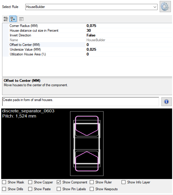
These parameters help define the geometric and contextual constraints for automatically generating stencil pad protection using a house-shaped perimeter. The house rule is recommended for chip packages, but can be used for all pins with clear directions.
Note: If the pin is under the body the direction cannot be calculated and no house is created.
Depending to the chip size it is recommended to change from house to inverted house rules.
| Property | Type | Description |
|---|---|---|
Corner Radius (MM) |
double | Rounding on the corners. |
House distance cut size in Percent |
int | Value in percent depending to the height of the pad. |
Invert Direction |
bool | For smaller elements sometimes the house fhould be show away from the component. |
Max Size of one Element (MM) |
double | Each element has maximum width and height, if the size is bigger it is automatically splitted in more elements. The value is in MM! |
Undersize Value (MM) |
double | All elements will use this value in mm to generate undersize pads. |
Offset to Center (MM) |
double | Move houses to the center of the component. |
Step for Big Elements (MM) |
double | If the element is bigger Max Element Size it use this value to split the size in more elements. |

These properties are used in the StencilScriptInvertedHouse class to define how shapes (such as stencil pads or vias) are duplicated and transformed. In general this rule is used for Chip Packages.
Note: If the pin is under the body the direction cannot be calculated and no house is created.
The StencilScriptSimpleSurface class defines the necessary parameters to create a rectangle structure around a stencil pad for solder paste applications. It is used for automating stencil generation and includes helpfull options.
| Property | Type | Description |
|---|---|---|
Corner Radius (MM) |
double | Corner radius for rounded elements in MM. |
Try Find Direction |
bool | Rotate surfaces depending to the direction of the pin. |
Rotate Bridges 45 Degrees |
bool | All bridges are rotated 45 degrees to obtain diagonal openings. |
Offset to Center X (MM) |
double | Move rectangle in X direction from the center of the pin. Or if you use negative values away from center. |
Offset to Center Y (MM) |
double | Move rectangle in Y direction from the center of the pin. Or if you use negative values away from center. |
Bridge Width (MM) |
double | Use bridges to cut the rectangle with this width. |
Bridge Count X |
int | Use bridges to cut the rectangle with count in X direction. |
Bridge Count Y |
int | Use bridges to cut the rectangle with count in Y direction. |
Offset move away disctance (MM) |
double | Move surface away from center point, this is only for outer pins (not for cooling pins). |
Size Width in MM |
double | Width for this pad. |
Size Height in MM |
double | Height for this pad. |

These parameters help define the geometric and contextual constraints for automatically generating stencil pad protection using a rectangle-based-shaped perimeter.
Note: The simple rectangle rule ignore the mask opening and overprint it!
The StencilScriptUsePinMinusMask class defines the necessary parameters to create a pin bases structure. It is used for automating stencil generation and includes geometry, shape characteristics, and spacing considerations.
This rule gives you the option to use the pin outline as basis with following options:
| Property | Type | Description |
|---|---|---|
Undersize Value in Percent |
double | All Elements will use this percent value on the smaller side to generate undersize. |
Undersize Value in MM |
double | All Elements will use this value in mm to generate undersize. |
Overwrite All Pins |
bool | Overwrite all pins regardless of the underlying pads. Set this property to false if you want to change single pins with different rules! |
Corner Radius (MM) |
double | Corner radius for rounded elements in MM. The value is independent of the undersize and can change the earthings with different values. |
Ignore Mask Layer |
bool | Take Pin without Mask Intersecting! This do not check overlappings and openings in the mask layer. |
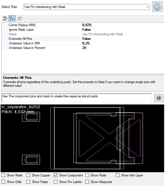
These parameters help define the geometric and contextual constraints for automatically generating stencil pad protection using the pin definition as basis.
Note: If the undersize values to small no pad will be created, the rule checks the mask layer for intersecting and it is a special handling for Overwrite All Pins to replace all pins with one rule!