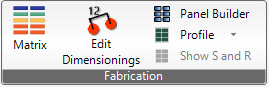
By clicking on the Panel Builder symbol, the following dialog will open:
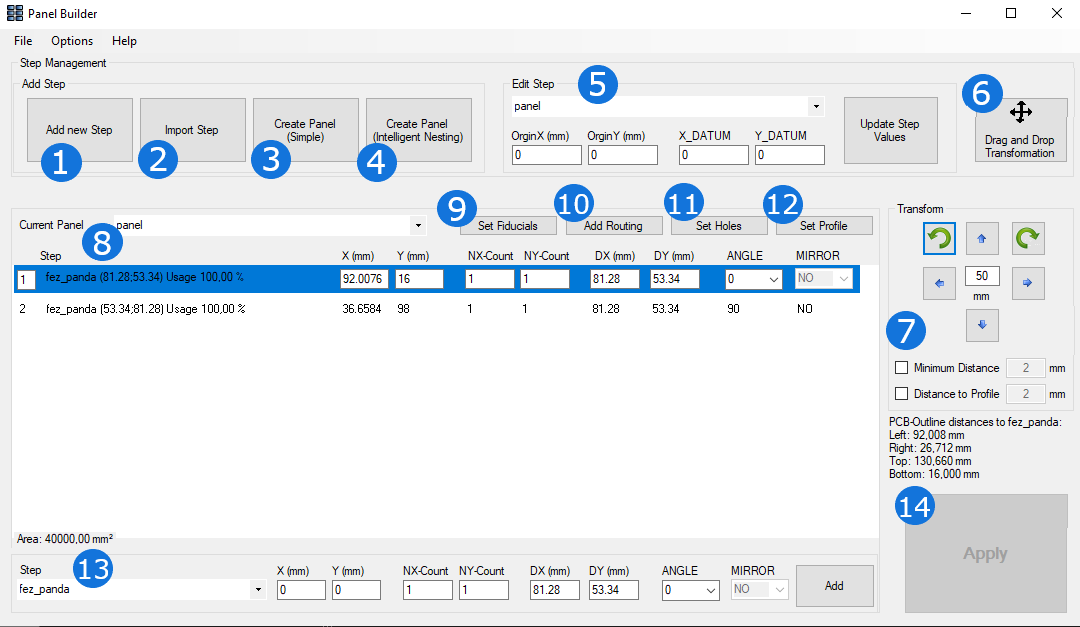
1. Clicking on "Add a new Step" enables you to create an additional step.
2. "Import Step" allows you to import a new design / step from another file.
3. "Create Panel (Simple)" is described separatly and in detail under the post "Create Panel (Simple)".
4. "Create Panel (Intelligent Nesting)" is also explicitly described in an extra post.
5. "Edit Step" is an additional functionality to be used to individually place the origin.
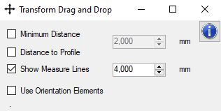
6. The "Drag and Drop" option allows you to manually place the steps on your panel. Clicking on it, the following dialog will open:
7. Clicking on a step in the list, you can transform the selected step by rotating it or moving it in individually set intervals.
8. This list shows all steps currently placed on the relevant panel with its most important information.
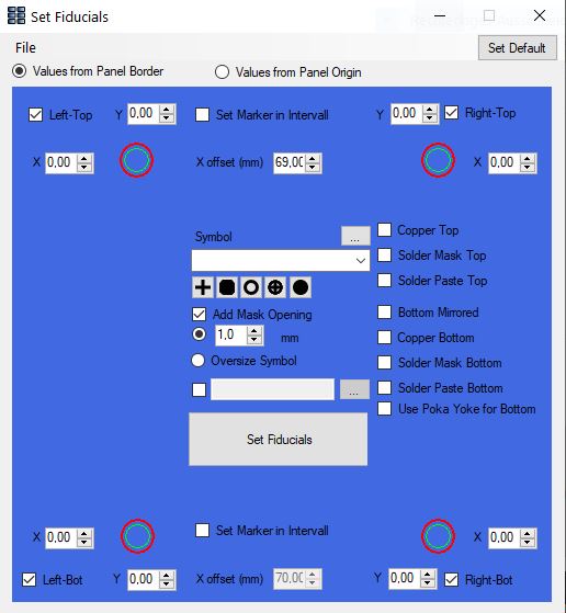
9. Clicking on "Set Fiducials" allows you to define markers on your panel. The following dialog will therefore open:
10. "Add Routing" is used to define the routing for your panel. Clicking on "Add Routing" will open the following dialog:
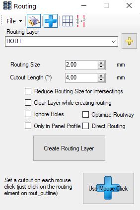
In the File menu you find an extra dialog "cutout editor" see here
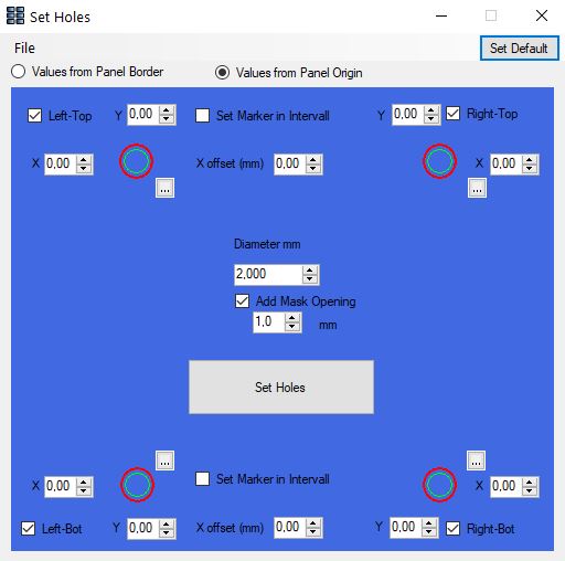
11. For defining holes on your panel, click on "Set Holes". The following dialog will be opened:
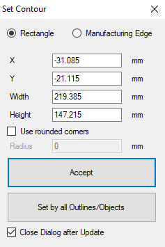
12. "Set Profile" allows you to define the profile of your panel. The following dialog will be opened when clicking on it:
13. Here, you can add another step on your current panel by choosing the step out of the provided list options. You are able to select each step that has been defined for this design.
14. Clicking on "Apply" applies all changes made by you on your currently opened design.
There are two ways to quickly create simple panels.
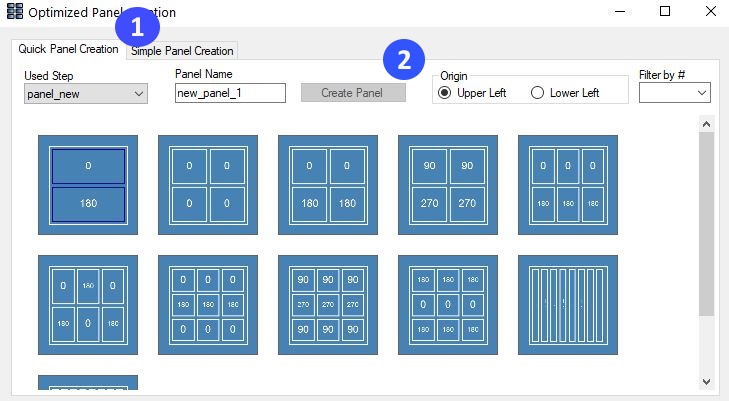
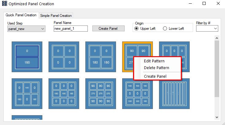
The two tabs switch between the generation according to the schema and the simple automatic generation. For simple automatic generation see Simple Automatic Generation. The window shows an already created schemata. The displayed schemes can be filtered by number, only those with a certain number of PCBs can be displayed. Expressions such as ">4" or "<=12" are also allowed to display only schemes with more than four or equal to or less than twelve PCBs. In the field "Panel Name" the name of the panel to be created is entered.
To create a utility according to one of the schemes, either select the scheme and click on the "Create Panel" button, or right-click on the scheme and select "Create Panel" from the context menu (see next picture). The small rectangles are the individual PCBs. The number in the rectangles is the rotation of the corresponding PCB and the yellow lines mark V-Shears.
The following view shows the context menu when right-clicking on a schema. The selected schema is bordered in orange.
This image shows the editor for creating and editing schemata.
1. With "Count Y" and "Count X" the number of PCBs can be set between each other (Y) or next to each other (X). A click on the button "Refresh Preview" will update the view
2. The following settings can also be defined:
With the "Export" button, the schema can be exported as an XML file. The button "Save" saves the schemata in the directory of the design. The key combination "Ctrl+S" can also be used to save the schema.
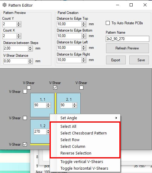
3. The view contains a preview of the schema. With the checkmarks V-Shears can placed between the corresponding rows/columns. The number fields can be used to adjust the angles of the individual fields of the schemata. To edit several fields at the same time, they can be selected with "Shift+left-click". A right-click on one of the fields opens the following context menu.
4. The button "Chessboard Pattern" selects the fields according to a chessboard pattern. The button "Reserve Selection" inverts the selection. A click on "All" selects all fields of the scheme. A click on "Row" selects all fields which are in the same line as the field previously selected by right-clicking. The button "Column" works like "Row", but selects all fields of the same column. All selections can be combined by holding down the shift key.
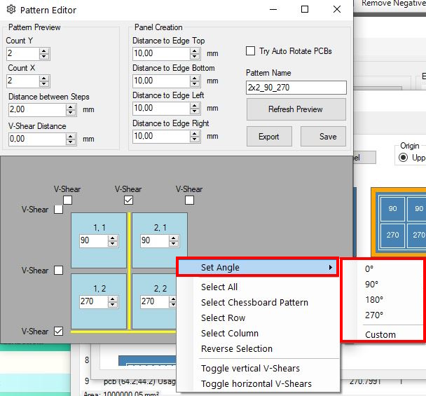
In the submenu "Set Angle" a common rotation can be assigned to all selected fields. 0°, 90°, 180° and 270° are available for preselection. By clicking on the "Custom" button, any angle from 0°-360° can be specified and assigned at 1° intervals.
With the help of this tool, simple labels can be created quickly and automatically. The PCBs are arranged according to their surrounding rectangles to save as much space as possible.
The Nesting Panel Optimizer automatically generates space-efficient panels from one or more designs.
Settings
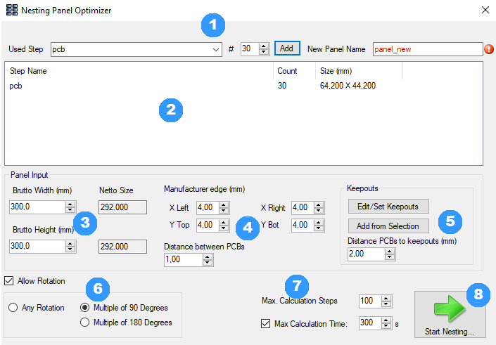
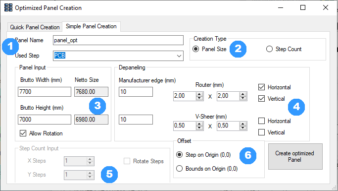
1. The desired design can be selected in the dropdown menu and added by clicking on the "Add" button in the set number. The currently selected design in the main window is preset. Please note that you should set the expected number that fits the use. Otherwise it can take a long time until a good solution is found. In the "New Panel Name" field, enter the name of the panel to be created.
2. In this window, the designs to be placed are listed with their set number. The dimensions (width x height) of the design are displayed in the right column.
3. Here, the dimensions of the blank can be entered. "Gross Width" corresponds to the total width of the blank, "Gross Height" to the total heigt. The net values refer to the area minus the distance that must be kept to the edge (see 4.).
4. These settings define minimum distances to the edge and between the designs.
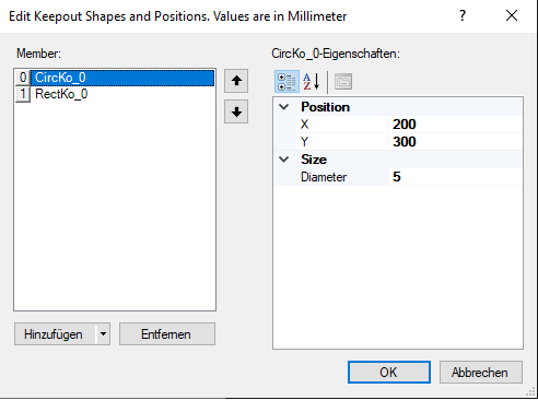
5. These buttons can be used to define areas on the panel which should remain free. The "Add from Selection" button creates areas from the objects selected in the main window and adds them to the list. Areas that are not within the use are ignored. Both buttons open the window below. New areas can be created and existing ones edited or deleted in the opened menu. The coordinates at "Position" refer to the center of the area.
6. If the check mark for "Allow Rotation" is not set, the PCBs are not rotated to achieve a possibly better utilization. If the check mark is set, the following options are available:
7. Via "Max. Calculation Steps" you can set the number of attempts after which the calculation should produce a better result. "Max. Calculation Time" indicates the maximum time the calculation should run before it is set automatically. The time limit can be deactivated if desired.
8. This switch starts the automatic generation with the settings made.
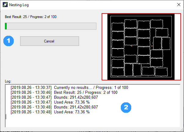
Running Time
When the automatic generation is started, this windows opens. It provides an overview of the current status of the calculation.
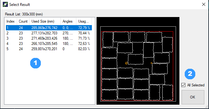
Result
As soon as the automatic panel generation has been aborted or completetd, one or more desired results can be selected in the following window to create a panel in the main window.
Panel Builder brings an template manager with it, there are options to store panel templates and an coupon library online or local.
With the templates you can use standard panel sizes with fix drill and marker positions. It is possible to store templates for each layer count, depending to the size of the useable area it calculate the amount of single PCBs in the template.
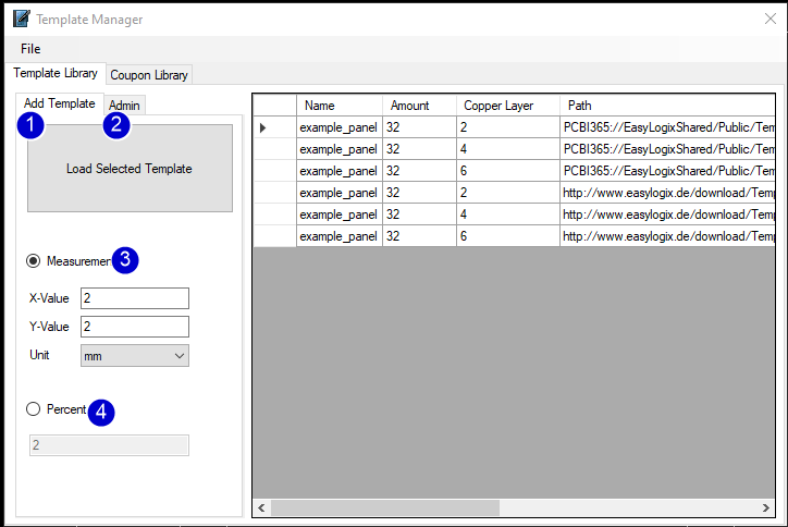
1) Add Template from the list on the right side
2) Change to Admin area
3) Options for distance in fix values
4) Option to fit single pcb with percent distances
Admin Area

1) Add the current design as template to the list.
2) Remove the selected template from the list.
3) Open the update dialog with many more options (useable ares, copper layer count, path to the template and step name)
Coupon Library
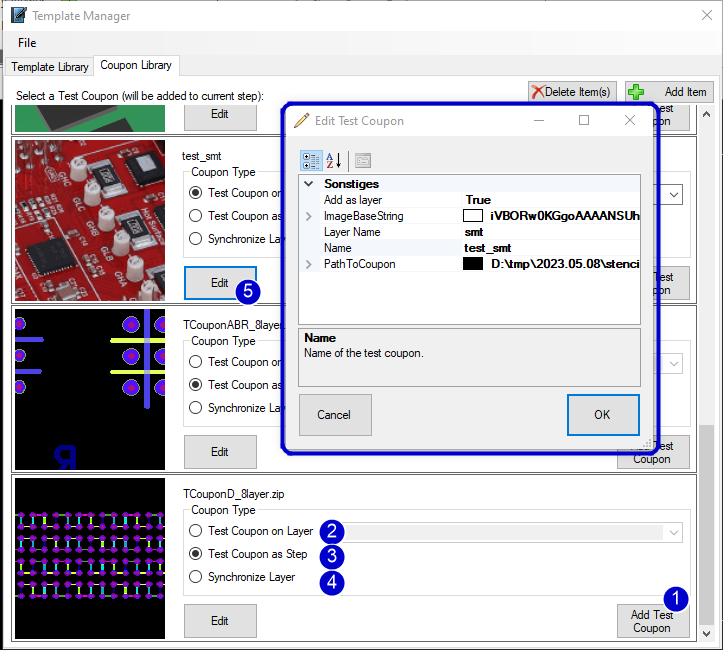
1) Add the selected coupon to the panel.
2) select "Test Coupon on Layer" to add the loaded coupon entry on one layer.
3) select "Test Coupon ad Step" to create an new step with all coupon information (recommended for coupons with components and net information)
4) select "Synchronize Layer" to fit the coupon data on the panel layers.
5) Edit the coupon entry, e.g. change image or path to the coupon.
The Cutout Editor helps you to create additional elmenets and modify the cutouts:

1) List of all cutouts, they have an running ID and a Location X/Y for special cutouts there is also and End X/Y and an repeat Index (for each child step).
2) Edit area for the cutouts, you can modify the Location.
3) Additional Element Area, here you can define what you need on different layers
4) Auxilary Drills is special, you can generate mousebites for one or both sides.
For setting mouse bite drills we have a second video:
Production panels perfectly utilized with Panel Optimizer

Create perfectly utilized production panels with the Panel Optimizer tool! Stop wasting expensive space and optimize the arrangement of your in-house panels for the final production! This will not only enable you to significantly reduce your production costs, but it will also speed up your time-to-market. Panel Optimizer automates the process of arrangement and therefore helps you to quickly find the ideal solution for your individual requirements.
In addition, the newly integrated traffic light system instantly indicates the actual capacity utilization of the production panels. At the same time, our optimization suggestions point out to you which changes of your panels can benefit a perfect utilization of the production panels. This enables you to find the best possible and most cost-efficient solution!
There are two ways to use Panel Optimizer:
1. Start the tool directly and input data directly (design size)
2. Start the tool out of PCB-Investigator, it gets the sizes and meta data from there and has an image with panel information
Here is a video how to use the tool: