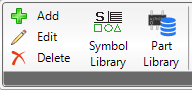
To edit objects, you first have to select the object you want to choose for edition (either by double-clicking or by using the selection tool). After that, by clicking on “Edit”, the following window will open showing the parameters of the currently selected object.
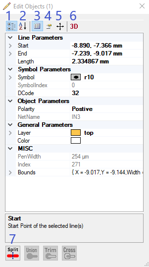
There are 4 general options of editing objects:
1. You can either sort the properties by categories or
2. according to the alphabet. It´s also possible to change the properties by entering new values.
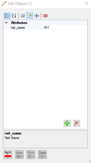
3. You will also see all attributes belonging to the selected object. By clicking on the green plus symbol, you can add attributes. The red cross will remove the selected attribute.
5. Editing the objects also refers to changing their position by moving, rotating or oversizing them.
Here, you have some different options to adjust the current position of the selected object. You can move (in specific steps per mm) and rotate your object (change angle) or oversize the object by entering new values for its size or a certain percentage for the augmentation.
6. It´s also possible to look up the 3D Step File Path that is deposit for the currently selected object. You can also adjust the 3D parameters by changing the values for the offset and rotation regarding X, Y and Z axis.
7. At the bottom part of the dialog, you can see 4 further options for editing objects (only the applicable ones will be shown in colour):
This feature allows you to create a dynamic text in the PCB-Investigator.
By adding "$$" and the keyword "DATE" you have the possibility to create a text in the board with several informations.
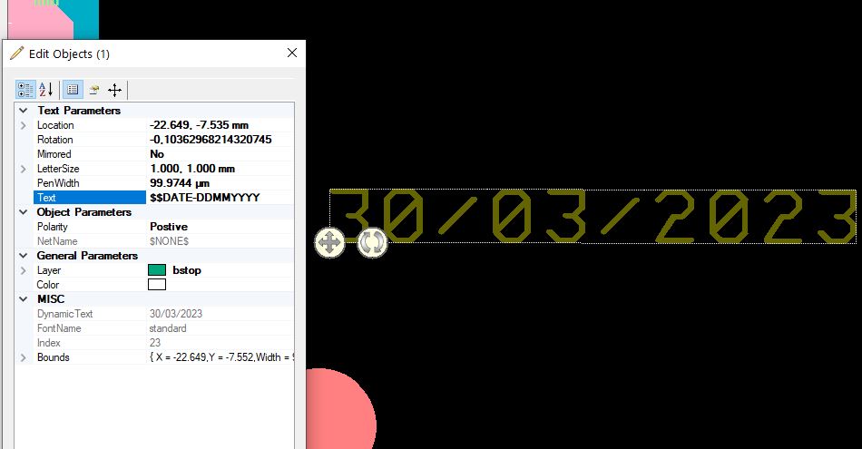
The following options are:
In PCB-Investigator there are many options to edit or set the PCB-Outline/Profile:

1. Set by Rectangle: This allows you to draw a rectangle with your mouse cursor
2. Set Rectangle by Selection: It creates the profile around all selected objects, this is always the bounding box rectangle
3. Edit Profile: this opens an extra dialog similar to surface edit in the edit dialog
4. Set by all Objects: sets an rectangle profile around all objects
5. Get Bounds: This show a message box with the size and offset of the current step
6. Clear Outline: With this button you can clear the outline and remove all existing profile elements.
7. Add active Layer(s) to Outline: You can add the active layer to the profile, be carefull maybe you have to Clear Outline first.
8. Add Selection to Outline: By selecting important objects like drill holes or routings you can add them to the existing outline.
9. Create Layer from Outline: This create a new layer with lines and arcs on it to export or modify the profile, if you use Add active Layer(s) to Outline (7) after Clear Outline (6) you can use the modified profile
10. Set from Selection Middle: to use online the middle of your selected lines and arcs you can override the existing profile e.g. by an routing way
11. Add from Selection Middle: this is the same like 10 but do not override the existing profile, it only adds the closed way in the selection
12. Set from Selection Holes: with this option you can use only the inner area of an routing way or a hole in an surface for the profile
13. Set PCB Outline: this allows you to define the profile with many mouse clicks