The SIPLACE QD Exporter is able to create placement lists and boards on ASM machines by creating '.qd' files with all needed information.
With the "SIPLACE QD Exporter" tool, you can create '.qd' files including placement lists and board information for ASM machines.
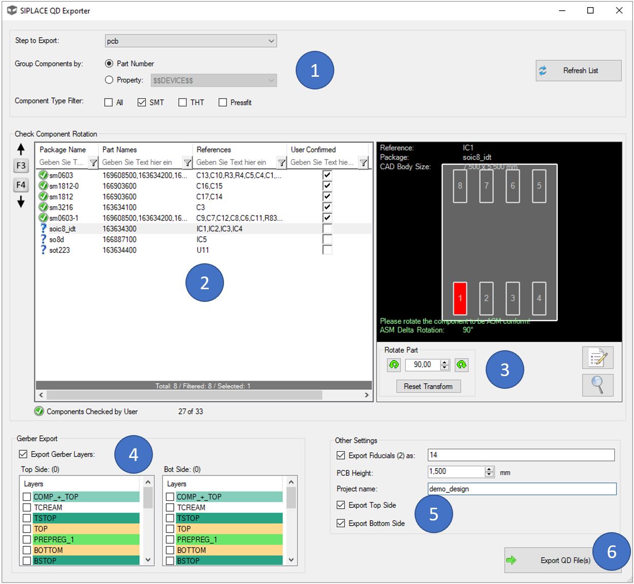
To start, you have to do a few settings in block (1):
Always when you change settings in (1), you will have to click at 'Refresh' to update the list. In the list (2), you will see all packages and the corresponding parts for each step or sub-step of your selected (panel) step.
It is then important so select list entry by list entry to check the rotation correction. If a entry is selected, you'll see the package drawing on the right side. You have to rotate this package to be displayed in exactly the same way, as it is defined on the ASM machine ('make it ASM conform'). You can confirm this by checking the "User Confirmed" checkbox in the list's last column. The rotation can be done by using the buttons in (3). Here, the rotation can also be reset and with the two buttons in this block on the right, you can open the property dialog of the CAD component or zoom to it.
In the block (4), you can choose which CAD layers should be exported as gerber files next to the '.qd' file. These gerbers can then be also imported in SIPLACE. The mirroring/translation of the bottom gerber is already done in the gerber itself, so that you do not need to transform the layers in SIPLACE.
In the block (5), there are different options available:
When clicking the 'Export QD File(s)' button (6), you are asked to select a folder where the files are exported to.
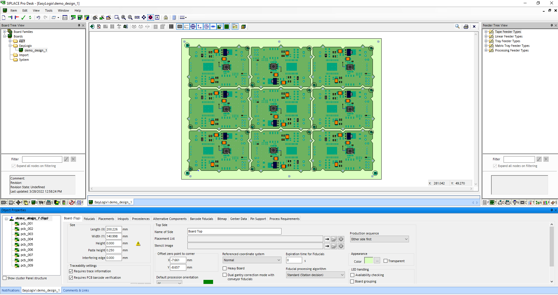
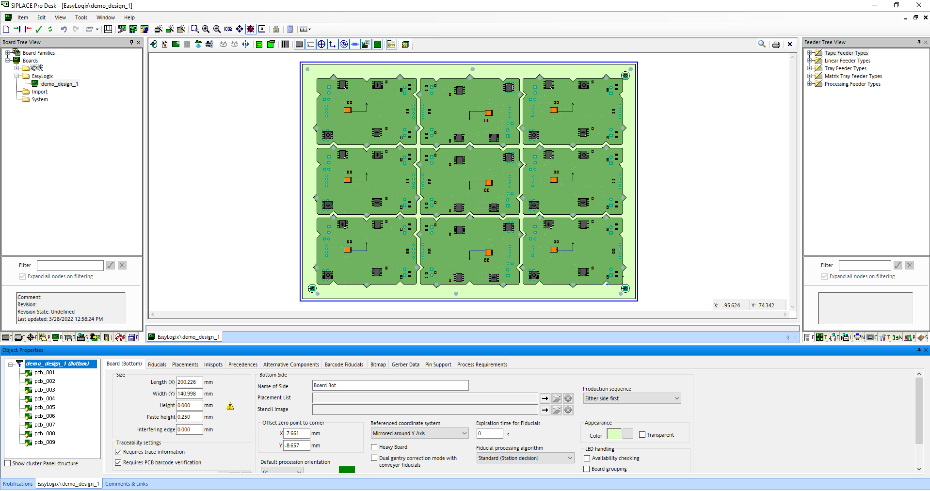
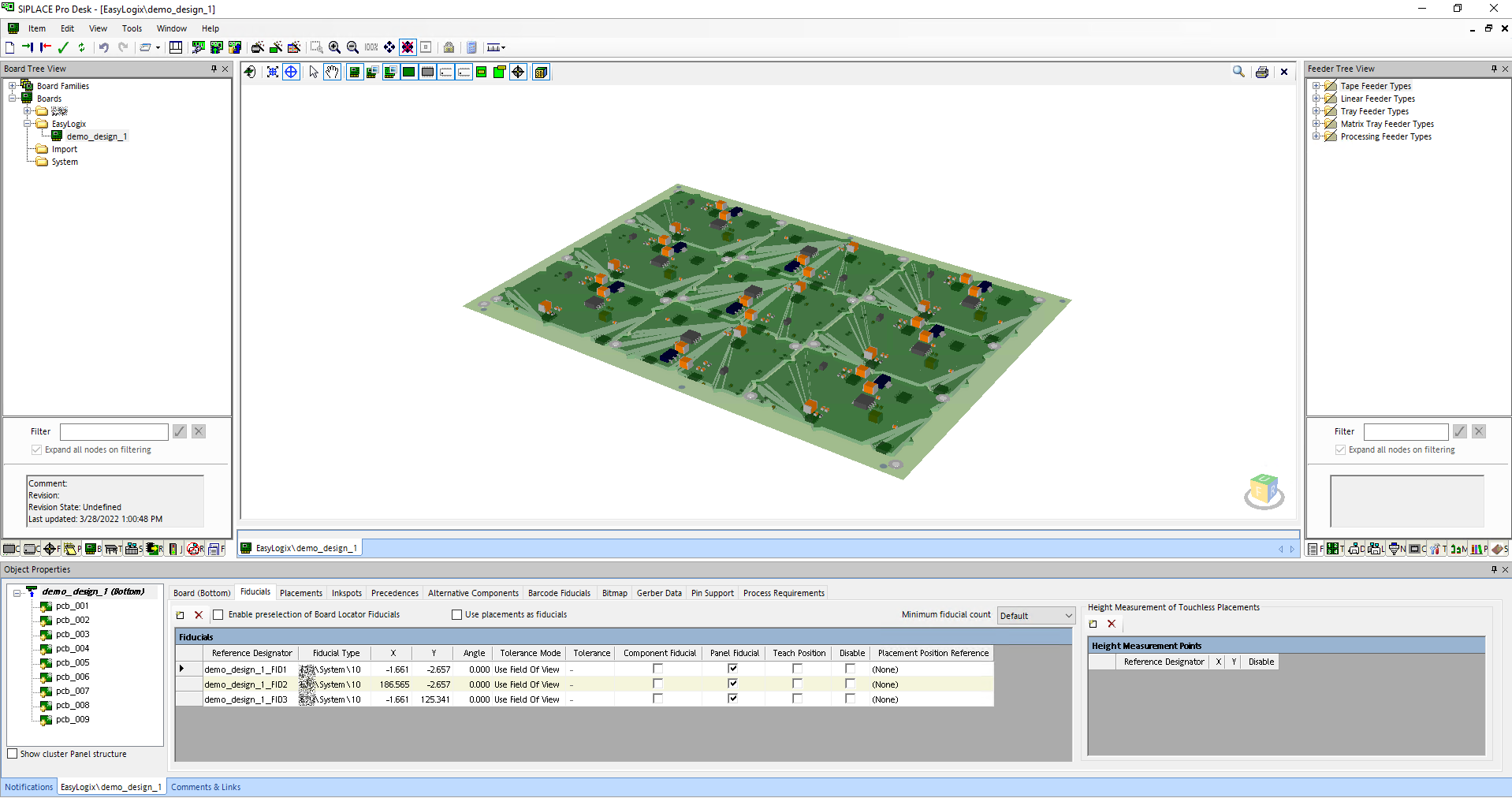
Here are some screenshots of the result in the SIPLACE Software: