There are two ways to quickly create simple panels.
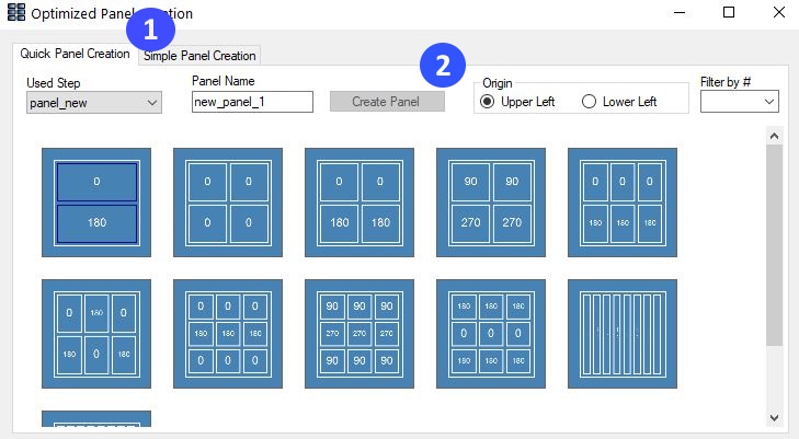
The two tabs switch between the generation according to the schema and the simple automatic generation. For simple automatic generation see Simple Automatic Generation. The window shows an already created schemata. The displayed schemes can be filtered by number, only those with a certain number of PCBs can be displayed. Expressions such as ">4" or "<=12" are also allowed to display only schemes with more than four or equal to or less than twelve PCBs. In the field "Panel Name" the name of the panel to be created is entered.
To create a utility according to one of the schemes, either select the scheme and click on the "Create Panel" button, or right-click on the scheme and select "Create Panel" from the context menu (see next picture). The small rectangles are the individual PCBs. The number in the rectangles is the rotation of the corresponding PCB and the yellow lines mark V-Shears.
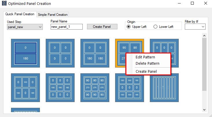
The following view shows the context menu when right-clicking on a schema. The selected schema is bordered in orange.
This image shows the editor for creating and editing schemata.
1. With "Count Y" and "Count X" the number of PCBs can be set between each other (Y) or next to each other (X). A click on the button "Refresh Preview" will update the view
2. The following settings can also be defined:
With the "Export" button, the schema can be exported as an XML file. The button "Save" saves the schemata in the directory of the design. The key combination "Ctrl+S" can also be used to save the schema.
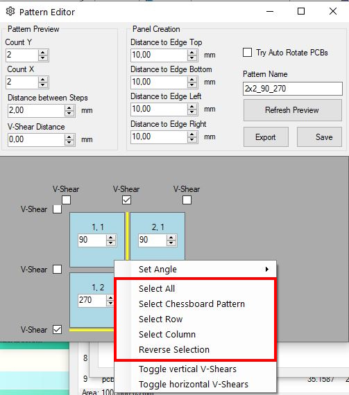
3. The view contains a preview of the schema. With the checkmarks V-Shears can placed between the corresponding rows/columns. The number fields can be used to adjust the angles of the individual fields of the schemata. To edit several fields at the same time, they can be selected with "Shift+left-click". A right-click on one of the fields opens the following context menu.
4. The button "Chessboard Pattern" selects the fields according to a chessboard pattern. The button "Reserve Selection" inverts the selection. A click on "All" selects all fields of the scheme. A click on "Row" selects all fields which are in the same line as the field previously selected by right-clicking. The button "Column" works like "Row", but selects all fields of the same column. All selections can be combined by holding down the shift key.
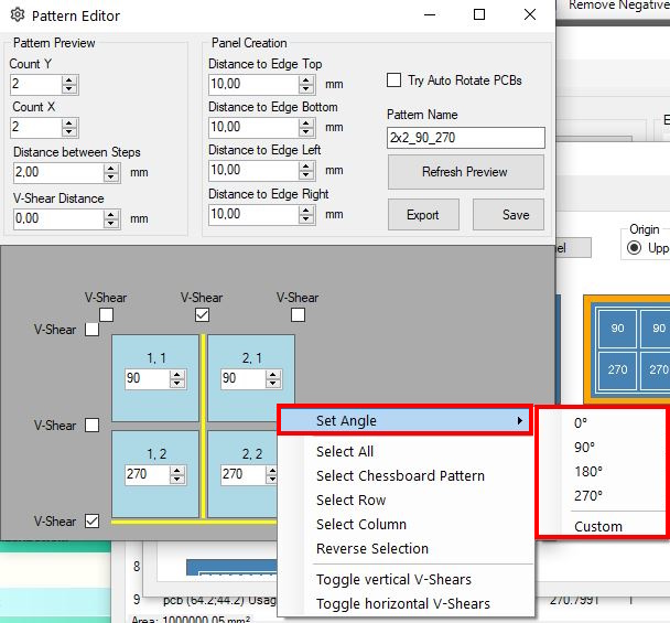
In the submenu "Set Angle" a common rotation can be assigned to all selected fields. 0°, 90°, 180° and 270° are available for preselection. By clicking on the "Custom" button, any angle from 0°-360° can be specified and assigned at 1° intervals.
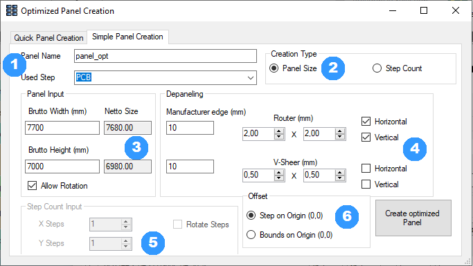
With the help of this tool, simple labels can be created quickly and automatically. The PCBs are arranged according to their surrounding rectangles to save as much space as possible.