After defining an operation state, you can now add all further passive components into the simulation model.
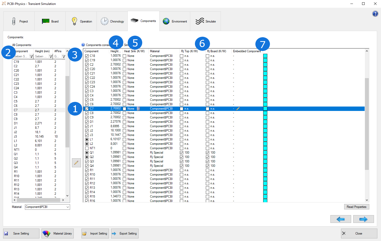
All components considered in the operation states are already included in the table and marked with a painted box (1). You can´t deactivate them as they are powered in the simulation state, but you can add a heat sink and adjust the material.
The list includes all components that will be considered in the simulation.
Therefore: Add all components which will influence the temperature of the board. This includes all components with a defined power loss (heat source) as well as components without power loss, as their existance (defined by size, height and material) also influences the temperature. They do not actively heat, but increase the board surface and by this is contributing to cooling. If you remove components, the result will be more incorrect as it won´t be considered in the simulation.
IMPORTANT: The bodies of components are not allowed to overlap or intersect each other! So please be careful with variants or large shielding components.
Now, select a reference designator (2) and add the components to the list (3). The component material normally is a non-conductive mixture material of plastic an metal. In the global material library, we have predefined three different component materials, low, high and very high metal percentage. For components with a bottom heat slug, we recommend "very high". Of course, you can define own materials, e.g. to simulate a printed component or a glued cermic part.
For all components considered in the simulation, the component height (4) must be defined correctly. The height can be changed/defined by clicking into the height cell of a component entry in the list on the right side. By unchecking a component entry in the list on the right side, you can deactivate this component in the simulation without deleting it from the list.
Another (optional) parameter considered in the simulation is the heat sink (5). The default heat transfer on the surface is replaced by the given thermal resistance (K/W) of an attached heat sink R_HS. Heat sink data must be found in the manufacturer's data sheet. However, a thermal resistance value Rth depends on area A. Only Rth*A is independent of the area. Normally, the data sheet heat sink does not exactly have the same base area as the component. Then, the data sheet value must be converted according to the following rule "Rth_comp = (A_DS : A_comp) x Rths_DS".
(Convert correctly if the data sheet specifications are in inch².)
The two-resistor model (for junction temperature Tj) (6) is a parameter that can also be considered optionally. If you do not specify the value, it is given as unspecified (n.s.). To estimate the junction temperature, you need instructions on how to transport heat from the junction to the surface and/or to the board inside the component. Sometimes you can find these instructions in the component's data sheet. In the model of the component´s body, it is no longer a bulk average but equal to "junction". An isothermal node is created with the help of a material Rj Special. The node is connected to the surface by Rj Top and to the board by Rj Board. The displayed result (numeric and graphical) now is the junction temperature Tj!
Advise:
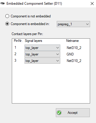
The last optional parameter is Embedded (7) and refers to components that are neither on the top nor on the bottom layer, but on a prepeg layer. The ODB++ format cannot represent this special position of components, but for thermal simulation the exact position of components is quite relevant respectively unnecessary result distortions could occur. Therefore, you can specify - if necessary - whether a component is embedded in a prepeg layer. The corresponding contact layer can also defined at this point.
To achieve a thermal equilibrium, the board has to be cooled. A good cooling environment (e.g. when strong fans are present) will lead to a low temperature and suppressed cooling (e.g. in an enclosure) to a high temperature (at same power).
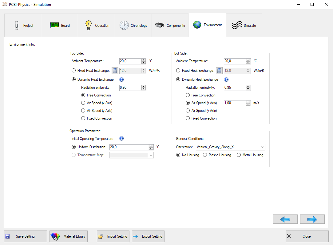
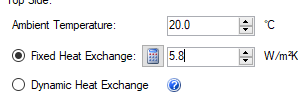
Ambient temperature:
The air temperature in vicinity of top and bottom side.
Fixed Heat exchange:
One way to simulate cooling is to perform a hydrodynamic flow field calculation, which is by far too time consuming and not appropriate for our purpose. PCB-I uses an approach known from mechanical engineering. The quantity, which can parameterize the heat flux to the ambient, is called heat transfer coefficient h (W/(m²K)). The larger h, the more effective heat can flow to the ambient. h is not a material property! PCBI-Physics uses a total value h, which is the sum of convective and radiative contribution.
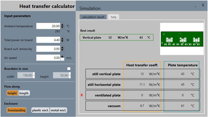
Heat exchange calculator:
A standard value for h is between 10 to 12 W/m2K. But h depends on power, the board size, the board orientation and the ambient air temperature. The calculator gives a good estimate working in most situations.
Dynamic Heat Exchange:
The (total) Heat Exchange is assumed as a sum of a convective and radiative part. This option is available only in transient or pseudo-transient mode, for top and for bootm side.
First, you have to specify the radiation emissivity. Radiation is always calculated at all surface points depending on their temperature and the housing options. Radiation emissivity describes how a material or a body surface exchanges infrared radiation with its surroundings. The maximum emissivity value is 1.
The most commonly used are listed here:
For the convectional part, there are the following three options:
Operating Parameter:
Defining the initial operating temperature, you can choose between a uniform distribution of temperature or the temperature map. Furthermore, you have to determine the general conditions of the board, e.g. if there is a housing (plastic or metal) or not. The orientation is important for the simulation as it affects the convection of the board.
Procedure in case of a simulation abort: