Component View Setup which can be reached through developer » Component View Setup offers you a whole set of options to customise how component information is displayed.
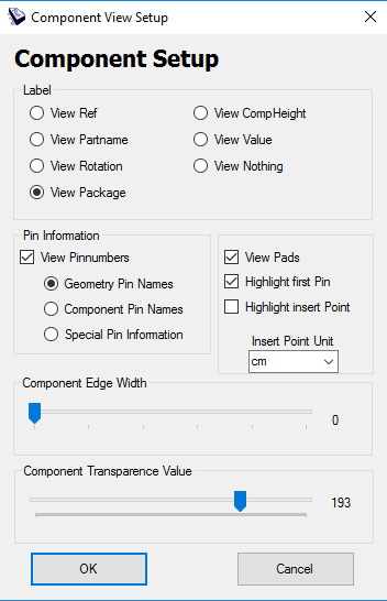
Label With the label option you can change which component information should be displayed on top of a component giving you a quick overview that may change depending on whether you are in development or fabrication. Possible labels include the part name, rotation and component height.
Pin Information View Pins: The first checkbox in the Pin Information panel determines whether pins generally should be displayed. Highlight first Pin: Activating the second checkbox fills the first pin of every component helping hardware developers to quickly recognize if diodes are correctly aligned. Highlight insert Point: File formats like ODB++ provide the optional possibility to state the centre of gravity of components. Activating the third checkbox lets this centre be displayed as a yellow dot. If no centre of gravity is specified in the data basis the middle of the component is used. Insert Point Unit: The dropdown allows you to change the unit used for the Insert Point option, for example, if a faulty unit was used in the data basis.
View Pin Numbers The checkbox determines whether pin numbers should be displayed while the radio buttons specify which data source should be used if the checkbox is activated. It is possible to either use the geometric definition of the component, the component reference (which can overwrite the geometric definition in file formats like ODB++), or special information which could be provided by a plug-in.
Component Edge Width The first slide control determines the line width of the outline.
Component Transparence Value The second slide control determines the opacity of components in the visualisation ranging from 0 (no filling) to 255 (completely filled).