The Nesting Panel Optimizer automatically generates space-efficient panels from one or more designs.
Settings
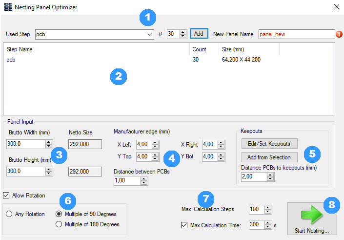
1. The desired design can be selected in the dropdown menu and added by clicking on the "Add" button in the set number. The currently selected design in the main window is preset. Please note that you should set the expected number that fits the use. Otherwise it can take a long time until a good solution is found. In the "New Panel Name" field, enter the name of the panel to be created.
2. In this window, the designs to be placed are listed with their set number. The dimensions (width x height) of the design are displayed in the right column.
3. Here, the dimensions of the blank can be entered. "Gross Width" corresponds to the total width of the blank, "Gross Height" to the total heigt. The net values refer to the area minus the distance that must be kept to the edge (see 4.).
4. These settings define minimum distances to the edge and between the designs.
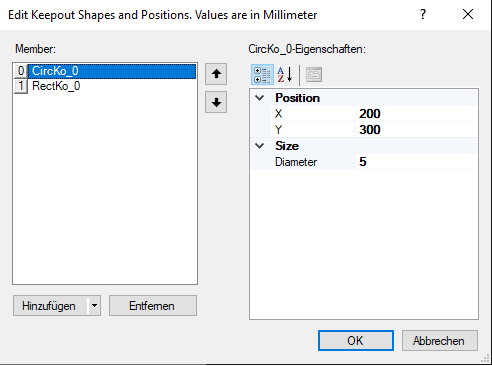
5. These buttons can be used to define areas on the panel which should remain free. The "Add from Selection" button creates areas from the objects selected in the main window and adds them to the list. Areas that are not within the use are ignored. Both buttons open the window below. New areas can be created and existing ones edited or deleted in the opened menu. The coordinates at "Position" refer to the center of the area.
6. If the check mark for "Allow Rotation" is not set, the PCBs are not rotated to achieve a possibly better utilization. If the check mark is set, the following options are available:
7. Via "Max. Calculation Steps" you can set the number of attempts after which the calculation should produce a better result. "Max. Calculation Time" indicates the maximum time the calculation should run before it is set automatically. The time limit can be deactivated if desired.
8. This switch starts the automatic generation with the settings made.
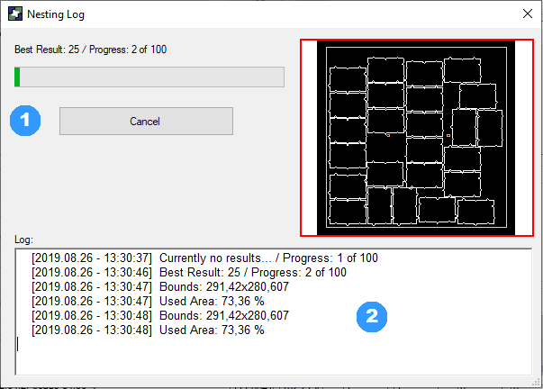
Running Time
When the automatic generation is started, this windows opens. It provides an overview of the current status of the calculation.
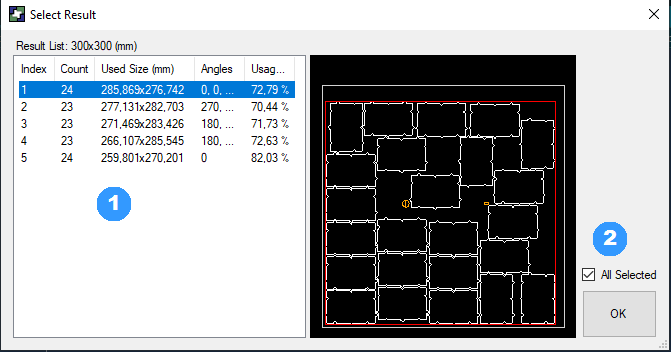
Result
As soon as the automatic panel generation has been aborted or completetd, one or more desired results can be selected in the following window to create a panel in the main window.