In the Operation tab, you can define different operation states you want to consider in your simulation.
To do this, you have two different options:
At first you have to create a new operation state by entering an appropriate operation state name. Then, you add the first component from the list which marks the starting point for defining a new operation state. Coming from this component, you choose an available net for the respective component for adding more components that you want to include in the simulation.
After that first step, you synchronize the selected component in PCB Investigator and add further component pins from the graphic interface as a sink to the net (right click). These two sinks build the basis for the list-based completion of the current path by multi-selecting the two parallel components and thereupon selecting the remaining components to be used for the respective current path.
Additional information for the components Q1/Q2: Pin ‘1+’ indicates, that all pins of this component connected to the same net are combined and considered as a single pin for the simulation (e.g. related to the current input). Number 1 in ‘1+’ refers to the name of the first pin in this net.
(Other example: if pin 17 and pin 18 of a component are connected to the same net, the pin name in Physics would be ‘17+’)
You now have two different options when defining the current flows. On the one hand, you can enter the power losses for each component and currents for each net using the conventional path (1).
On the other hand, there is a new, alternative way via the definition of pin bridges (2). Here, you just define the amount of current which is going through the current path in total, but you do not have to know and enter how the current is split up in each single net of e.g. parallel parts. Furthermore, the input of the power dissipation is omitted as it will be derived during the simulation by using the internal resistance (e.g. RDSON). Especially for parallel components, this input method has advantages, because you do not have to know how the current splits up, as this will be simulated by the tool using net lengths, copper structures, temperature depending material properties and component resistances.
 (1) Now the currents are to be defined. Energize particular nets by directly entering the corresponding values in the graph. Using multiselect, several components are marked and a fixed current can be set / split. The left side of the component marks the sink of the net, the right side the source. Thereby, you always have to keep the sum of the sources and sinks per net identical. It is possible that there are several pins of a component that cling together to only one net. You just have to enter the ampere of each pin. The current arrows then show you the sum. Furthermore, a fixed value for the power dissipation must be determined for each component. This value can be taken from your data sheets.
(2) The energization process can also be realized by defining pin bridges. In this example, the pin bridges are defined for each of the four components, whereby a fixed internal resistance is to be determined. Alternatively, you can specify the internal resistance as temperature-dependent. As soon as you have defined a pin bridge for a component, you can see how the pins within the component are connected graphically by an arrow.
Different from (1) the activation respectively the calculation of the power dissipation is done during the simulation based on the internal resistance of the pin bridges. Therefore, no fixed portion is given, but the formula P = R*I² (power dissipation = resistance x current²) will be applied. In addition, you can determine a fixed proportion as a base. Since the actual power dissipation of a component depends on the current according to the formula mentioned before, you will only find ">0" or ">fixed portion" at this point.
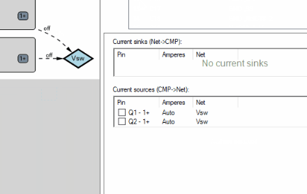
The activation of the current as well as the calculation of the current intensity for sources and sinks is done automatically (see green marking + "Auto"). By defining the pin bridges, the current path between the components is considered as if they were connected to a single large network. The current flows across all components with their defined pin bridges according to the conduction and component resistance. In the case of parallel components, the amperes are divided; the exact distribution results from the simulation, yet, if the internal resistances are the same, a 50:50 distribution can be assumed. Only for the last component in a current path the current has to be defined, in this case 1 ampere.
Copy the given operation state and multiply the currents and power losses with the chosen factor. Then, activate a new path in the operation state that has been inactive before.