The Component Report in PCB-Investigator is a useful tool to get a summary of all components used in the PCB. This can be very helpful to make sure that all required components are present on the board and to make sure that they are placed and wired correctly.
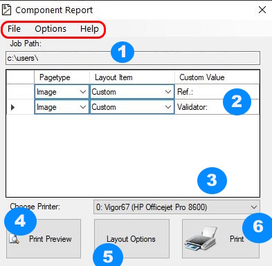
1. The path of the currently loaded job is displayed here
2. The window is for customizing temporary field contents of the layout.
All items of the layout type "Custom" are listed here. The changes are
only temporary.
3. With this button you can choose your printer
4. With this button you can see the print preview
5. At "Layout Options" you can set the options for creating the layout.
More about this in the following paragraph.
6. The Last Button is for printing your Component Report
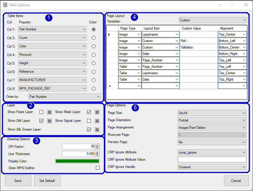
1. Tablepartitioning sets which attributes/properties of the CMP should be listed and which attribute/property should be used for coloring (Component with same attribute value get same color)
2. Layer options gives you the possibility to display different layers during printing
3. Drawing Options can be used to change the color or thickness if you like
4. Layout of the side is used to create your own page layout and can be extended as you wish.
Pagetype: Image or TableCustom Value: Will only be filled if the item was set to Custom before. Values filled here will be saved in the layout.
Alignment: Used to determine where on the page this element should be placed. Same alignments lead to the fact that these are arranged afterwards under each other.5. Page Options gives you the options in which paper format to print. In addition, you can select how many lines of the table should be displayed on one page (0 means that the table will have its own page). Furthermore you can sort the table by attributes and choose between predefined page layouts like:
all three layouttypes are shown in the print preview at the end of this page.
Page Arrangement is Important only for Rows per page = 0 (table on extra page)
It is possible to ignore components with different options to hide them or crossout them.