
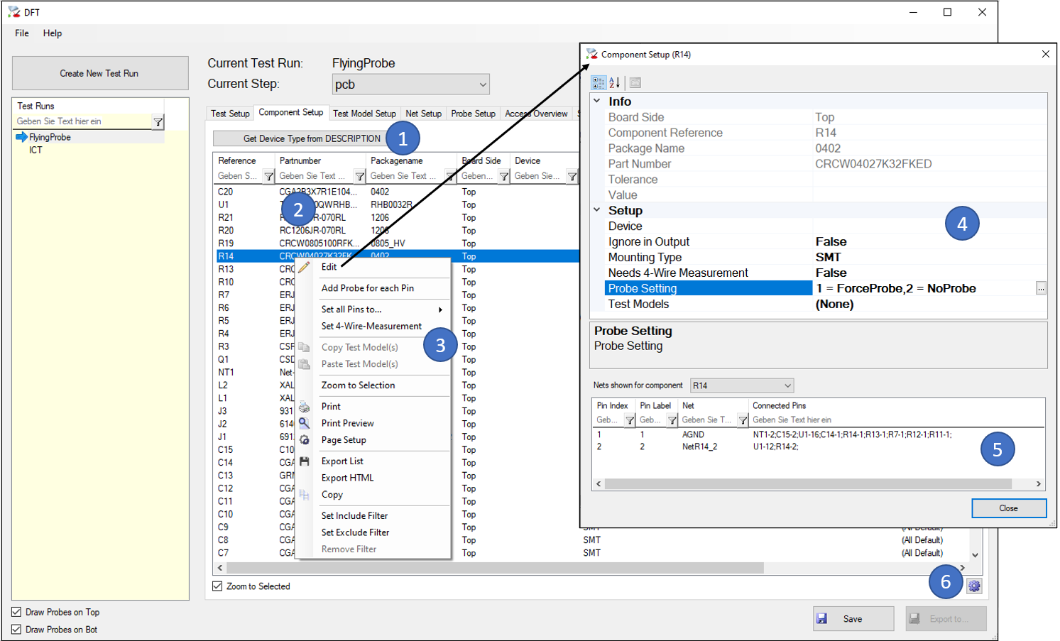
- This button fills the “Device” column in the list from the value of the DESCRIPTION Property of the components (if exististing).
- The list shows all components of this data step and allows you to add additional information to each component.
- In the context menu some important functions are easily accessible or the “Edit” (4) dialog can be opened.
- In the “Edit” dialog, you can correct the “Mounting Type” if it was not available in the imported layout data, you can define whether a component is really placed or if it is not in the BOM (“Ignore in Output = true”), and you can force or prohibit the probe generation for single pins. It’s also possible to define if 4-wire measurement is needed and the test model(s) for each single component, although it is recommended to do this in the “Test Model Setup” Tab (C) for all components of the same part number at once.
- This list gives you an overview of how the pins of the selected components are wired. This information may help to define test models, especially when it comes to define the pin types of Diodes (Anode/Cathode) or Transistors and others.
- With this button you can add own columns to the list by stating a property name, e.g. “MPN” for the material part number or “Manufacturer”. Of course, those properties must exist in the layout data.