The "Testpoint" option allows you to check the distance between testpoints and between testpoint and components. This analysis is important to ensure e.g. the manufacturability of ICT adapters.
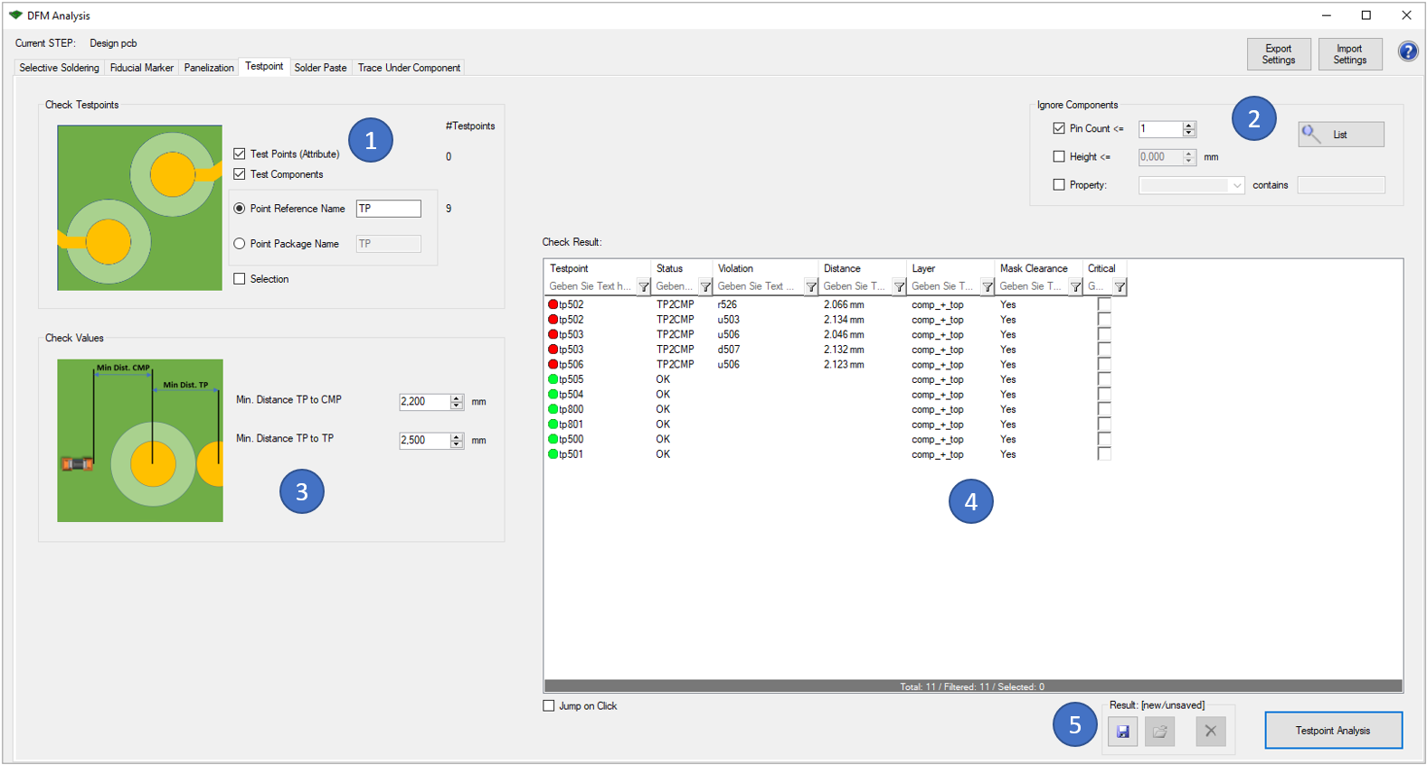
In the first block (1) there are different options to identify test points:
- By Attribute: The ODB++ ".test_point" attribute is used. This attribute might exist at test point copper pads on the outer layers.
- By Component Referenz: The component reference designator must contain e.g. "TP" (like 'TP120')
- By Component Package Name: The component package name must contain e.g. "TP" (like 'tp0.8')
- By Selection: Any selected component or copper pad is used as test point
With the block "Check Values" (3), you can enter the wanted distances between testpoints (center to center) or between testpoint and components (center to outline).
The results of the analysis are displayed in the window on the right (4). You can also view the analysis results directly in the tool. Critical errors can also be marked for later use (e.g. in the 'Extended Design Report').
Following picture shows an example error of this analysis:

A component is too close to the test point tp502.
The following functionalities are equally integrated in all six options:
- It is possible to exclude components from the analysis (2). You can do this either via "Pin Count", "Height" or "Property". Furthermore, a search function via "List" is available, which lists all excluded parts in an overview.
- With the buttons on the top right side of the window you can export the previously defined settings so that you can reuse them for later analyses. Already saved settings can be imported via the "Import Settings" button.
- The last result can be saved and reloaded with the buttons on the lower right side (5). This stored result is also used in the 'Extended Design Report'.
- Clicking on the question mark on the top right of the window opens the corresponding page of our online manual.