The i3070 export creates a “board” and “board_xy” file that contain all available component and net information to easily create the test program with the native machine software.
Following export settings are possible:
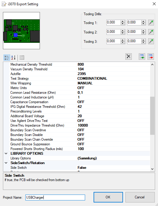
- Side Switch: If true, the PCB will be checked from bottom up
- Rotation: If >0, the PCB will be rotated clockwise by this angle (e.g. 90°) after applying the SideSwitch command (if SideSwitch=true)
- Fixture Type: Fixture Type
- Fixture Size: FULL, BANK1, BANK2
- Top Probes Allowed: ON/OFF
- Heavy Probe Force: Heavy Probe Force
- Light Probe Force: Light Probe Force
- Mechanical Density Threshold: Mechanical Density Threshold
- Vacuum Density Threshold: Vacuum Density Threshold
- Autofile: Autofile
- Test Strategy: COMBINATIONAL, EDGE CONNECTOR ONLY
- Wire Wrapping: MANUAL, AUTO, WIRELESS, SEMI AUTO
- Metric Units: ON/OFF
- Common Lead Resistance (Ohm): 0.1m ohm to 100 ohms.
- Common Lead Inductance (µH): 0.1n Henry to 1m Henry
- Capacitance Compensation: Capacitance Compensation
- IPG Digital Resistance Threshold (Ohm): IPG Digital Resistance Threshold, Value in ohms
- Preconditioning Levels: Preconditioning Levels
- Additional Board Voltage: 0-100
- Use Agilent DriveThru Test: Use Agilent DriveThru Test
- DriveThru Impedance Threshold (Ohm): DriveThru Impedance Threshold
- Boundary Scan Overdrive: ON/OFF
- Boundary Scan Disable: ON/OFF
- Boundary Scan Chain Override: ON/OFF
- Ground Bounce Suppression: ON/OFF
- Powered Shorts Shorting Radius (mils): 1-250
- Tolerance Multiplier: 0.1 - 10
- Remote Sensing: ON/OFF
- Fuse Threshold: Fuse Threshold
- Diode Current (A): Diode Current
- Zener Current (A): Zener Current
- Adjust: NONE, FAST, ACCURATE
- Upstream Disable: ON/OFF
- Upstream Condition: ON/OFF
- Test Strategy Cover Extend: BSCAN, HYBRID, HYBRIDGUARD, BSCANGUARD
- Family Options: Family Options contain a list of different family options with settings e.g. for TTL/ECL/LVC...
- Library Options: Library Options contain a list of library paths e.g. './custom_lib'
- Inductor Series-R (Ohm): Inductor Series-R Standard Value
- Transistor High Beta (V): Transistor High Beta Value (If value=0 in test model)
- Transistor Low Beta (V): Transistor Low Beta Value (If value=0 in test model)
- FET High Resistance Limit (Ohm): FET High Resistance Limit (0.1 Ohm - 1 MOhm)
- FET Low Resistance Limit (Ohm): FET Low Resistance Limit (0.1 Ohm - 1 MOhm)
- FET Enhancement Gate Voltage (V): FET Enhancement Gate Voltage (0-9V)
- Fuse Max Current (A): Fuse Max Current
- Failure Message: Failure Message (Value from Property: %PROP_NAME%)
- Failure Message (NOPOP): Failure Message for NOPOP components (Value from Property: %PROP_NAME%)
- Part number field: Part number field value (Value from Property: %PROP_NAME%)
- Part number field (NOPOP): Part number field value for NOPOP components (optional if not PIN LIBRARY) (Value from Property: %PROP_NAME%)
- Special Partname Rules: Rules to rename parts according their original name
- Export Component Outline: Export Component Outline in XY File (DEVICE Section)
- Merge all NC Nets: Merge all NC nets into a single NC net
- Export Transistor as PinLibrary: Export Transistor Model as PinLibrary
- Export FET as PinLibrary: Export FET Model as PinLibrary
- Export Diode as PinLibrary: Export Diode Model as PinLibrary
- Export LED as PinLibrary: Export LED Model as PinLibrary
- Export Zener as PinLibrary: Export Zener Model as PinLibrary
- Export Fuse as Jumper: Export Fuse Model as Jumper Close
- Export Inductor as Jumper: Export Inductor Model as Jumper Close
- Export Switch as Jumper: Export Switch Model as Jumper Close
- Probe Reference Prefix: Reference prefix for dummy components at probe locations
- Suppress Needle Sizes: Suppress Needle Sizes in XY-File (39MIL/50MIL)
- Export PartNumber and FailureString: Export Partnumber and Failure String for all components. If false, Partnumber and Failure String is exported only for PinLibrary components.
- Inductor Tolerance Addition (%): Inductor Tolerance Addition in %
- Resistor Tolerance Addition (%): Resistor Tolerance Addition in %
- Capacitor Tolerance Addition (%): Capacitor Tolerance Addition in %