Fixture Parameters:
Tester Type:
Tester Type to use for the automatic probe creation
Probe Side:
Search probes on this/these side(s)
Exclude Single-Pin Net:
Exclude No/Single-Pin Net, all no-pin and single-pin net entries will not create probe entries.
Use max. Test Resources from Net Setup:
If yes, only the given number of Probes are created. If no, all Probes are created
Search Tasks (Top):
Defines the tasks and the order for searching probes on top side
Search Tasks (Bot):
Defines the tasks and the order for searching probes on bot side
Available Needles:
All allowed needles for fixture probes. Will be used beginning with the largest one. Here also the needed distances to components are defined per needle definition
Standard min. Distance to Components:
If no special distance is defined for the given needle, this is the standard min. distance from probe center to surrounding components
Minimum Distance between Probes:
The minimum distance between Probes, measured from outline to outline (taking diameter of the Needle Definition into account)
TP Reference Filter List:
Comma separated reference filter list (e.g. \"TP, P\"). TP Components must start with one of these entries.
TP Pad Recognition:
Recognize test points by the '.test_point' attribute on copper pads.
Minimum pad size to use as probe (Top):
Minimum copper pad size to create a probe for top side.
Minimum pad size to use as probe (Bot):
Minimum copper pad size to create a probe for bot side.
Enable Solder Mask Analysis:
Enable Solder Mask Analysis, only round pads with openings in solder mask are used if this setting is active.
Minimum pad size to use as probe (Top):
Minimum pad size to create a probe for top side.
Minimum pad size to use as probe (Bot):
Minimum pad size to create a probe for bot side.
Maximum drill diameter to use as probe:
Maximum drill diameter to create a via probe.
Enable Solder Mask Analysis:
Enable Solder Mask Analysis, only round pads with openings in solder mask are used if this setting is active.
Minimum pad size to use as probe (Top):
Minimum pad size to create a probe for top side.
Minimum pad size to use as probe (Bot):
Minimum pad size to create a probe for bot side.
Minimum annular ring to use as probe (Top):
Minimum annular ring to create a probe for top side.
Minimum annular ring to use as probe (Bot):
Minimum annular ring to create a probe for bot side.
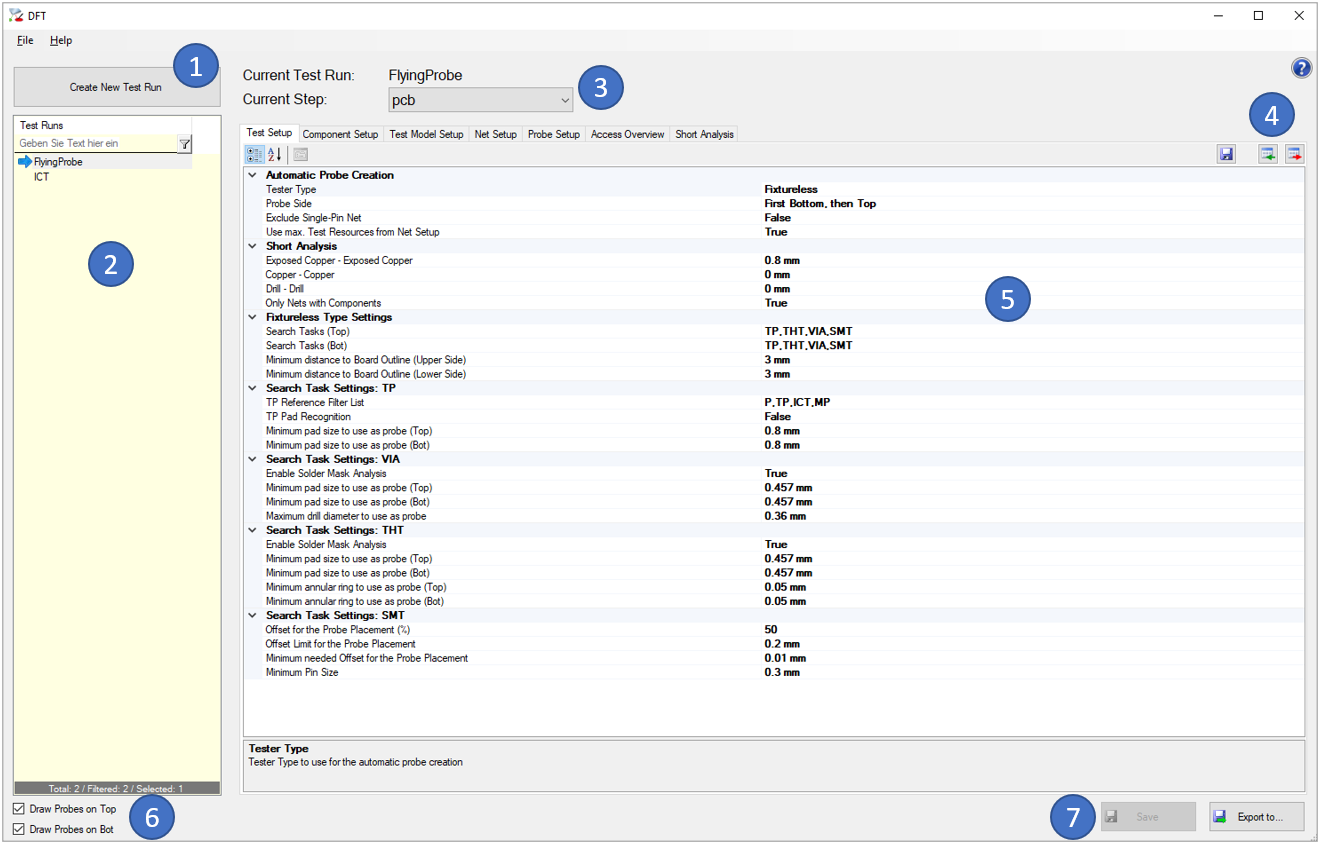
Fixtureless parameters:
Tester Type:
Tester Type to use for the automatic probe creation
Probe Side:
Search probes on this/these side(s)
Exclude Single-Pin Net:
Exclude No/Single-Pin Net, all no-pin and single-pin net entries will not create probe entries.
Use max. Test Resources from Net Setup:
If yes, only the given number of Probes are created. If no, all Probes are created
Exposed Copper - Exposed Copper:
The minimum distance between exposed copper areas to not be reported in the Short Analysis (0=deactivated)
Copper - Copper:
The minimum distance between any copper areas to not be reported in the Short Analysis (0=deactivated)
Drill - Drill:
The minimum distance between plated drills to not be reported in the Short Analysis (0=deactivated)
Only Nets with Components:
Only nets with components are checked
Search Tasks (Top):
Defines the tasks and the order for searching probes on top side
Search Tasks (Bot):
Defines the tasks and the order for searching probes on bot side
Minimum distance to Board Outline (Upper Side):
Minimum distance from fixtureless access point center to upper board outline
Minimum distance to Board Outline (Lower Side):
Minimum distance from fixtureless access point center to lower board outline
TP Reference Filter List:
Comma separated reference filter list (e.g. \"TP, P\"). TP Components must start with one of these entries.
TP Pad Recognition:
Recognize test points by the '.test_point' attribute on copper pads.
Minimum pad size to use as probe (Top):
Minimum copper pad size to create a probe for top side.
Minimum pad size to use as probe (Bot):
Minimum copper pad size to create a probe for bot side.
Enable Solder Mask Analysis:
Enable Solder Mask Analysis, only round pads with openings in solder mask are used if this setting is active.
Minimum pad size to use as probe (Top):
Minimum pad size to create a probe for top side.
Minimum pad size to use as probe (Bot):
Minimum pad size to create a probe for bot side.
Maximum drill diameter to use as probe:
Maximum drill diameter to create a via probe.
Enable Solder Mask Analysis:
Enable Solder Mask Analysis, only round pads with openings in solder mask are used if this setting is active.
Minimum pad size to use as probe (Top):
Minimum pad size to create a probe for top side.
Minimum pad size to use as probe (Bot):
Minimum pad size to create a probe for bot side.
Minimum annular ring to use as probe (Top):
Minimum annular ring to create a probe for top side.
Minimum annular ring to use as probe (Bot):
Minimum annular ring to create a probe for bot side.
Offset for the Probe Placement (%):
This parameter is used, if Probes are set to Pins where no TESTPROBE_KEEPOUT but a MPN Package Outline exists. The probe is placed on x % of the distance from the outer edge of the pin to the edge of the MPN Package Outline (also see next parameters). If a keepout is defined, the probe will be placed to the middle of the remaining pin contact area. If no MPN Package Outline is defined, 'Offset Limit for the Probe Placement' is used for the offset.
Offset Limit for the Probe Placement:
This parameter is used, if Probes are set to Pins where no TESTPROBE_KEEPOUT exists. The offset distance calculated with 'Offset for the Probe Placement (%)' is limited to this value, so the offset will not be larger as this value. If no MPN Package Outline exists, this value is used for the offset.
Minimum needed Offset for the Probe Placement:
This parameter is used, if Probes are set to Pins where no TESTPROBE_KEEPOUT but a MPN Package Outline exists. If the offset distance calculated with 'Offset for the Probe Placement (%)' is smaller than this value, no Probe will be placed.
Minimum Pin Size:
Minimum Pin size to be used for the Probe Placement (width and height must be larger/equal