Trace Under Component

The "Trace Under Component" option allows you to check, if certain components have unallowed copper tracks under their body between their pins. This is mostly unwanted for small 2-pin components, as it can cause problems during soldering.
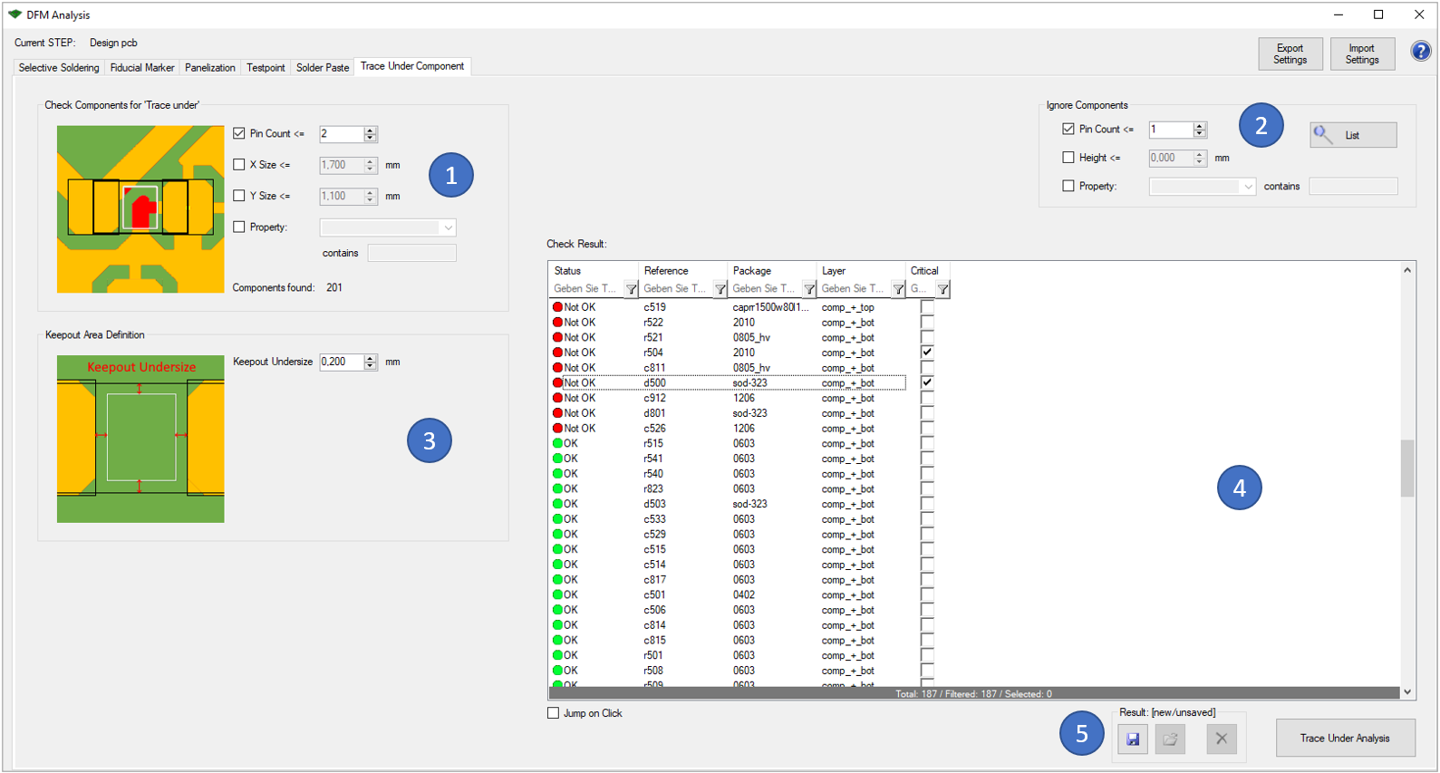
In the first block (1) there are different options to identify the components that should be analyzed:

  • Pin Count: Only components with e.g. <=2 pins
  • X Size: The x size should be less than the entered value
  • Y Size: The y size should be less than the entered value.
  • Property: A given property must contain a certain value string

With the block "Keepout Area Definition" (3), you can enter the wanted undersize that is used to determine the keepout area under the component body and between its pins. 

The results of the analysis are displayed in the window on the right (4). You can also view the analysis results directly in the tool. Critical errors can also be marked for later use (e.g. in the 'Extended Design Report').

Following picture shows an example error of this analysis:
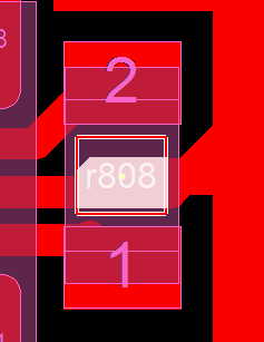
The component "r808" has unwanted copper tracks under its body inside the keepout area.


The following functionalities are equally integrated in all six options:

  • It is possible to exclude components from the analysis (2). You can do this either via "Pin Count", "Height" or "Property". Furthermore, a search function via "List" is available, which lists all excluded parts in an overview.
  • With the buttons on the top right side of the window you can export the previously defined settings so that you can reuse them for later analyses. Already saved settings can be imported via the "Import Settings" button. 
  • The last result can be saved and reloaded with the buttons on the lower right side (5). This stored result is also used in the 'Extended Design Report'.
  • Clicking on the question mark on the top right of the window opens the corresponding page of our online manual.