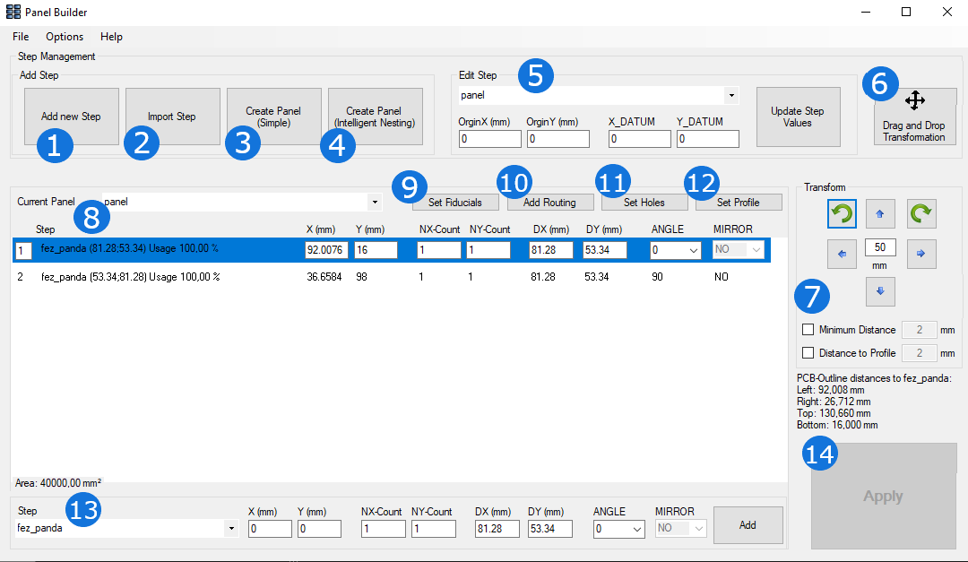
By clicking on the Panel Builder symbol, the following dialog will open:
1. Clicking on "Add a new Step" enables you to create an additional step.
2. "Import Step" allows you to import a new design / step from another file.
3. "Create Panel (Simple)" is described separatly and in detail under the post "Create Panel (Simple)".
4. "Create Panel (Intelligent Nesting)" is also explicitly described in an extra post.
5. "Edit Step" is an additional functionality to be used to individually place the origin.
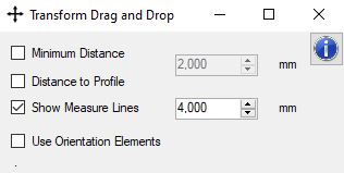
6. The "Drag and Drop" option allows you to manually place the steps on your panel. Clicking on it, the following dialog will open:
Minimum Distance: Minimum Distance to another step that should not be deceeded.
Distance to Profile: Minimum Distance to the profile.
Show Measure Lines: Measure lines for a better handling of drag & drop.
Use Orientation Elements: Orientation elements for facilitating drag & drop.
7. Clicking on a step in the list, you can transform the selected step by rotating it or moving it in individually set intervals.
Minimum Distance: Minimum Distance to another step that should not be deceeded.
Distance to Profile: Minimum Distance to the profile.
8. This list shows all steps currently placed on the relevant panel with its most important information.
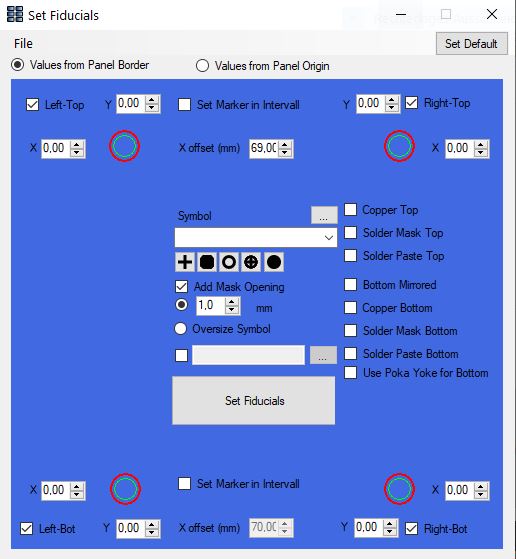
9. Clicking on "Set Fiducials" allows you to define markers on your panel. The following dialog will therefore open:
You can either use the values from the panel border or from the origin of the border.
If you want to place markers, you can select the starting point (left-top, right-top, left-bot, right-bot) from which they are to be placed and - if needed - the interval (X offset) that defines the spacing of the placement.
You have the choice between four default marker symbols; you can also load another symbol out of the default options or choose an own symbol from a library if needed.
You can also choose to add a mask opening; the size of this opening can be adjusted individually in mm. This also gives you the option to oversize the symbol.
You also have the option to add components. To do this, you just need to select one from your Package Library.
Before setting the fiducial markers (Click on "Set Fiducials"), you have to select the propriate layer/s where you want or need to place the markers.
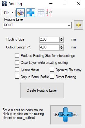
10. "Add Routing" is used to define the routing for your panel. Clicking on "Add Routing" will open the following dialog:
On the top of the dialog, there are four symbols to be further explained (from the left to the right):
1. Symbol: For checking for components placed nearby.
2. Symbol: Use for multiply cutouts.
3 Symbol: Use to clean double cutouts.
Routing Layer: Choose the layere you want to use for routing.
Routing Size: Select the size of the routing.
Cutout Length: Adjust the length of your routing cutout/opening.
Reduce Size for Intersecting: It is possible to change the routing diameter for small gaps or near child steps.
Clear Route Layer: Remove all existing routings for new calculation.
Ignore Holes: Create Routing only for ourline elmenents.
Optimize Routway: Check for overlapping with near child step routings and remove double routings.
Only in Panel Profile: Depending on your edge handling this can help to place less routings and remove all routings outside of the panel.
Direct Routing: Place the routing lines direct on the outline of child steps, for some export formats the routing can be handled with shifting (left or right) to get the correct result.
Only in Vshears: Check Vshear lines on the selected layer, for some cases the routing should be only in some areas.
Components Outside: Use an oversize for overlapping components, this is needed for assemble in panel.
After the creation of the routing layer, you can "Use Mouse Click" to define a cutout for each mouse click. You just have to click on the intended routing part to set a cutout.
In the File menu you find an extra dialog "cutout editor" see here
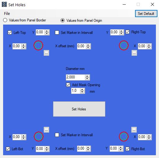
11. For defining holes on your panel, click on "Set Holes". The following dialog will be opened:
Like described in "9. Set Fiducials", this dialog works practically analogously.
There is the possibility to decide for the hole shape for each position (left-top, right-top, left-bot, right-bot) by clicking on : You can either decide for an oval form or a round shape.
You can define the diameter of the holes to be set in mm.
To set the holes like defined before, just click on "Set Holes".
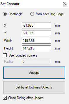
12. "Set Profile" allows you to define the profile of your panel. The following dialog will be opened when clicking on it:
You have the option between setting the contour according to a rectangle or a manufacturing edge: Depending on your choice you have to set different parameters.
Rectangle: You have to define the x and y axis as well as the width and height of your profile in mm. If needed, you can select to use rounded corners (you therefore have to define a suitable radius)
Manufacturing Edge: You have to define the size of left, right, top and bottom of your profile in mm. You can also decide for rounded corners.
By clicking on "Accept", the current size of all active layers will be calculated. If there is no active layer, all loaded layers will be used instead
By clicking on "Set by all Outlines/Objects", all loaded objects will be used for the calculation.
13. Here, you can add another step on your current panel by choosing the step out of the provided list options. You are able to select each step that has been defined for this design.
14. Clicking on "Apply" applies all changes made by you on your currently opened design.