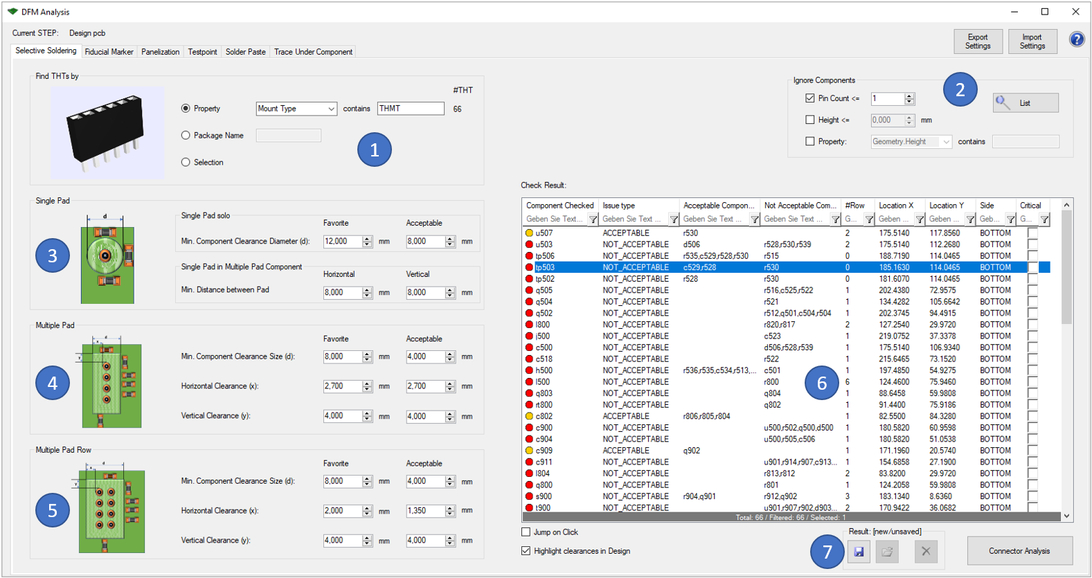
To begin with, the first topic is "Selective Soldering". This checks whether the set THT components will fit at the given location or whether the pins or holes of the THT component may be too close to components on the opposite side. The THT components you want to check can be selected either by the property or by the package name. It is also possible to directly select the THT components (1).
Before you can start the "Connector Analysis", you have to define the settings for the analysis. There is a distinction between "Single Pad" (3), "Multi Pad" (4) and "Multi Pad Row" (5). For each case, you can individually define the settings that will be used for the analysis. The pictures are intended to illustrate these variables. Each variable is determined by two different values, the "favorite" or optimum value and the "acceptable" value up to which manufacturability (according to your specifications) is still guaranteed.
The results of the analysis are then displayed in the table on the right-hand side of the window (6). Right-click to export them in HTML format. You can also use the tool to display the result. Components in the yellow area are located in the range you have defined as still acceptable. If a component is within the red area, the producibility with the current design is not guaranteed or the specifications defined by you are not fulfilled. Critical errors can also be marked for later use (e.g. in the 'Extended Design Report')
Following picture shows an example error of this analysis:
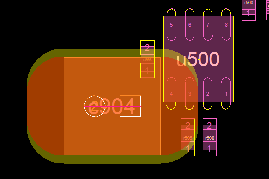
The THT component c904 is located on top side, but soldered on bottom side. The yellow marked components are too close to the soldered pins according to the 'Multi Pad' rule. The red area shows the "Acceptable" area, the yellow one is the "Favorite" area.
The following functionalities are equally integrated in all six options: