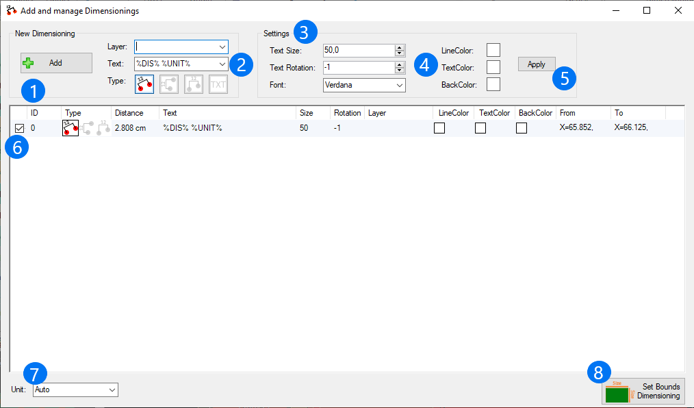
1) After you have adjusted the settings for the next dimensionings you want to add, you can press "Add".
Then, move to the graphic interface to choose two points on your printed circuit board you want to select for measuring their distance. PCB-Investigator thereby helps you with reference points to easily mark e.g. the edge or centre of a component. To set a marker for dimensioning use a right-click. A double-click allows you to change the location of the set marker by entering new values for x and y. You can also easily relocate the connecting line and its associated text information with holding the right mouse botton and shifting the line in its wanted position.
2) Here, you can adjust the settings for the layer, the text and the type of the new dimensioning you want to add.
3) There are three more options you can adjust before adding a new dimensioning: text size, text rotation and font.
4) You can also determine the colors that should be used for the visualization of the dimensioning: line color, text color, back color.
5) Clicking on "Apply" allows you to subsequently change the settings of (3) and (4) for all dimensionings you have determined so far at once.
6) In this list, you will find a overview of all dimensionings you have determined with all their relevant information. You can also adjust the settings by double-clicking on the intended configuration. A right-click on a dimensioning will highlight the appropriate dimensioning in the graphic interface.
7) Here, you can choose the unit you want to use for your dimensionings. Selecting "auto" will apply an automatically choosen unit (most practical solution) for each dimensioning. To avoid misunderstandings using "auto", you should indicate the unit for each of your dimensionings (2).
8) "Set Bounds Dimensionings" sets the dimensionings for your overall printed circuit board (lenght, width).
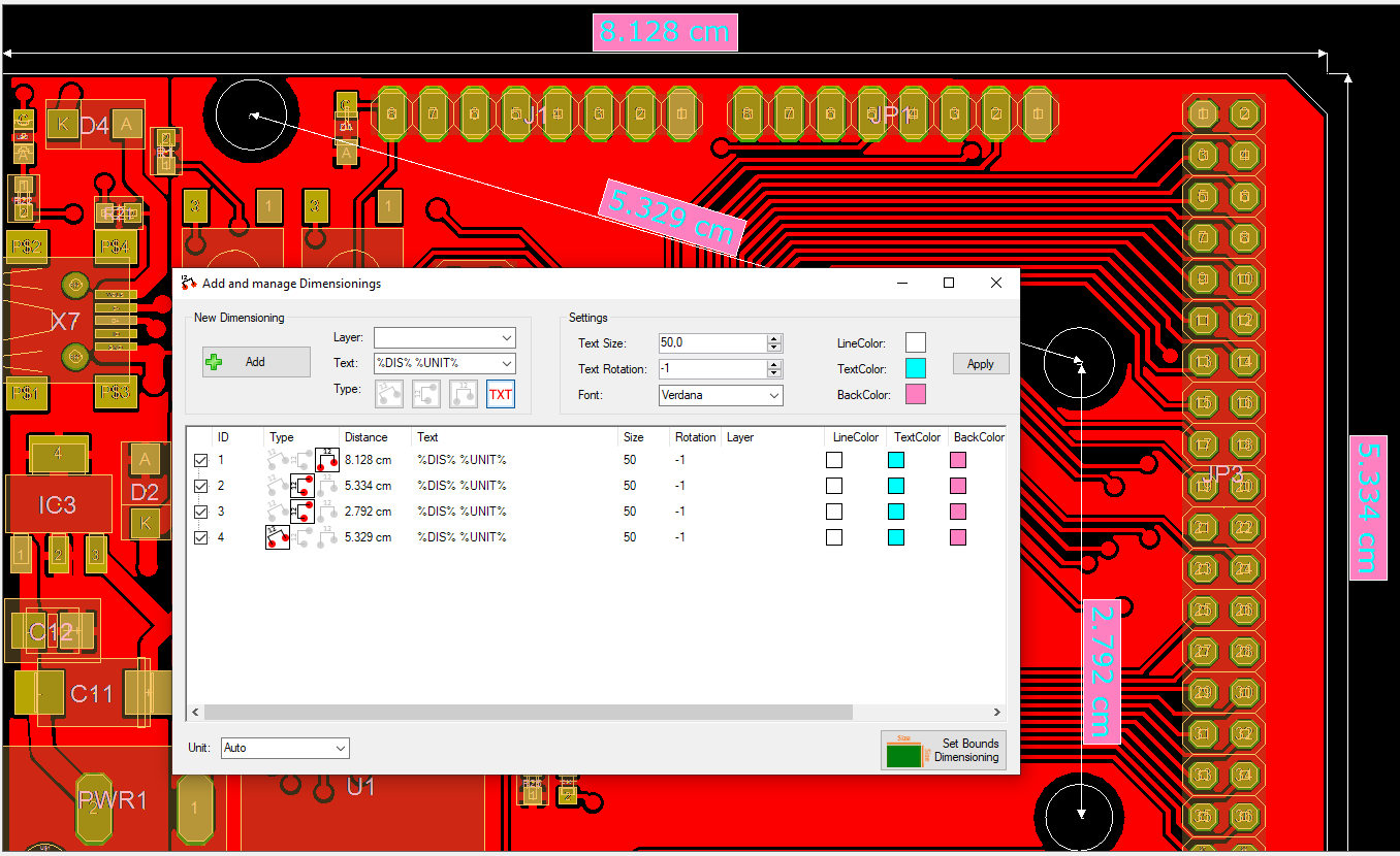
Example for dimensionings on a design:
View Dimensionings:
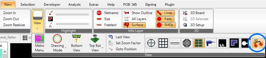
To display or hide your dimensionings, click on the framed symbol which can be found under "View".