The NetGroup Wizard can be used to create net groups and to add or remove nets to them.
Open the NetGroup Wizard with clicking the "Net Groups" button.
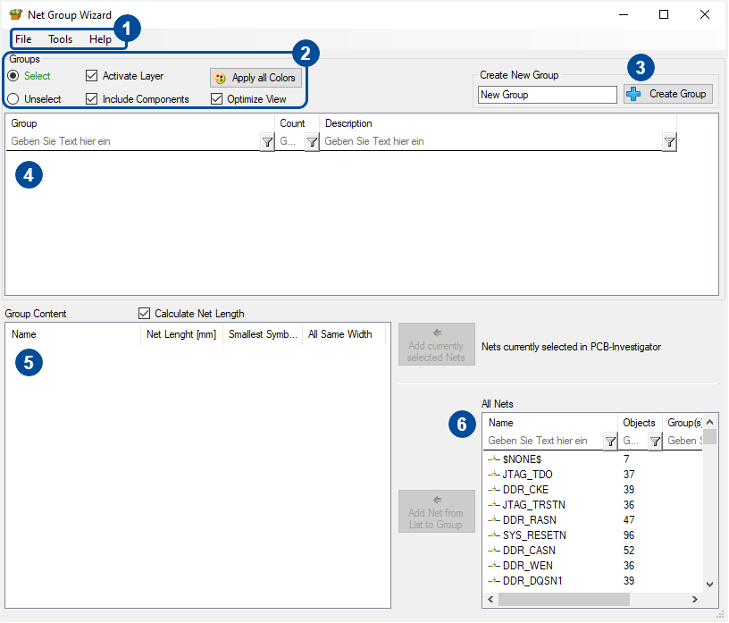
The following dialog will show up.
1. The two important tabs contain the following options.
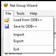
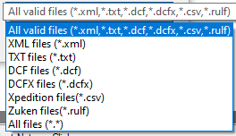
The net groups are always stored within the ODB design. Sometimes, you want to import net groups from another design. Prior to that, export the current net group to have a backup of them. In the import you can select between different file formats (xml, txt, dcf, dcfx, csv, rulf) to add net groups from other software (e.g. Xpedition or Zuken) or if you select xml from other PCB-Investigator exports.
Import Format List:
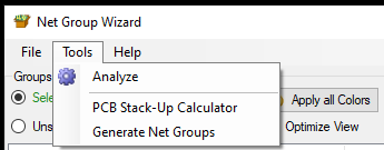
The "Tools" tab has three important functions.
Analyse (see next chapter): Clicking the analyse control, a new dialog will open.
The PCB Stack-up Calculator is a calculator for the PCB stack-up.
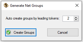
Generate Net Groups: If you want to generate net groups automatically, you can use the "Generate Net Groups" contol. Clicking this option, will open the following dialog.
To create net groups, the net names will be used. The number is the number of letters to be tapped. All nets with the same beginning will then be added to the net group. The net groups names depend on the tapped letters.
2. The summary of controls allow you the following operations:
Select: The "Select" control can be used to focus the selected net group.
Unselect: If you selected multiple net groups, you can deselect one or more net groups to isolate the net groups you want to inspect.
Activate Layer: This allows you to see the layers nets of the net groups when selecting a group.
Include Components: "Include Components" also shows you the connected components to net nets of the net groups that you are selecting.
Apply all Colors: If the net group has been colored, the "Apply all Colors" button allow you to color all nets with the same color.
Optimize View: With this option you can zoom to the area of the net group and all included nets.
3. The button "Create Group" allows you to create you own groups with the desired group name.
4. This control contains all net groups which are deposited in the ODB dataset. More options to edit net groups can be found by right clicking on a net group.
Rename: Here, you can rename the net group
Add Description: You can add text that will be shown behind the group name in the extra tab.
Assign Color to Group(s): Using this functionality, you can assign a color to the group within the list. It won´t assign color to the nets on the design.
Apply Color in PCB-Investigator: If you assigned a color to the group, you can now assign this color to the nets included in the net group. Now, the nets will be shown in the design with the same color.
Zoom to the Net Group: Here, you can zoom the net group. If you double left click a net group entry, you will also zoom to the net group.
Remove Color Assignment: Use this function to remove color assignments.
Delete/ Delete All: You can either delete the selected net group or all by using either "Delete" or "Delete All".
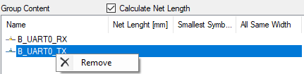
5. Every net of the net group will be shown here, if a group in the group view (4) is selected. To remove a net of the net group, right click the net you want to remove and click remove.
6. If y net group (4) is selected, you can add single nets to the net group with clicking a net in the view with the number 6 and clicking the add button. There are two different add buttons:
The upper add button will just add nets which are selected on the design. If no net is selected, the button can´t be used.
The button below adds the nets you select in the bottom right net list.