To start, please select a server and click "Connect" (1).
With the "Placement List Creator" tab, you can create placement list elements for each component side on the OIB server.
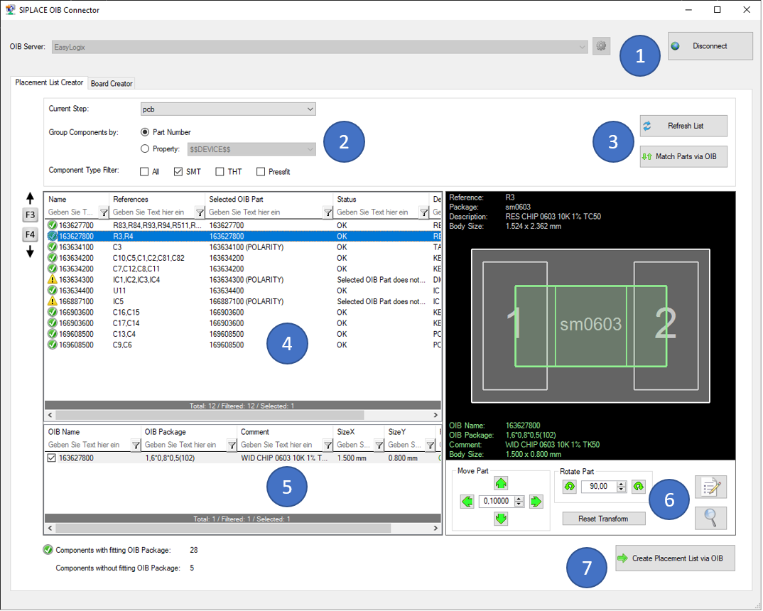
To start, you have to do a few settings in block (2):
Always when you change settings in (2), you will have to 'Refresh' the list and 'Match Parts via OIB' again (3).
When the matching process is done, you will see all your filtered parts in the list (4), including an overlay of the matching OIB part definition on the selected server. Found OIB parts are centered on the CAD package center. Details of the found OIB part and the fitting state are listed on the bottom side (5).
The 'Status' column indicates, whether a OIB part was found or not, and if the found part fits onto the CAD package. The condition for fitting is, that the pin definition of the OIB part must at least partly overlap the CAD package pin.
If the found part does not fit, you have the possibility to shift its position or to rotate it until it fits (6). With the two buttons in this block on the right, you can open the property dialog of the CAD component or zoom to it.
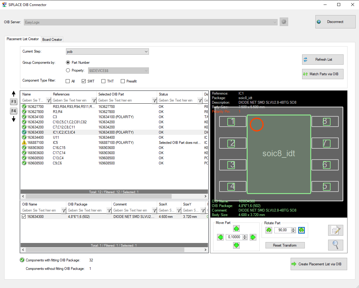
If the OIB part has a polarity definition, this polarity marker is visualized in red. The fitting alorithm then also uses the polarity information, to recognize if the component is correctly rotated (CAD polarity pin is same as OIB polarity pin).
Example of the fitting process (6) (by rotating 90° clockwise):
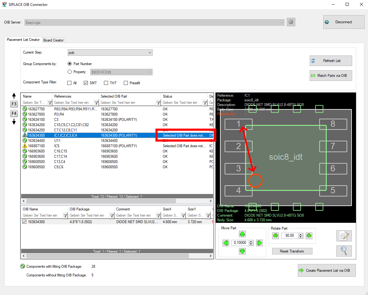 =>
=> 
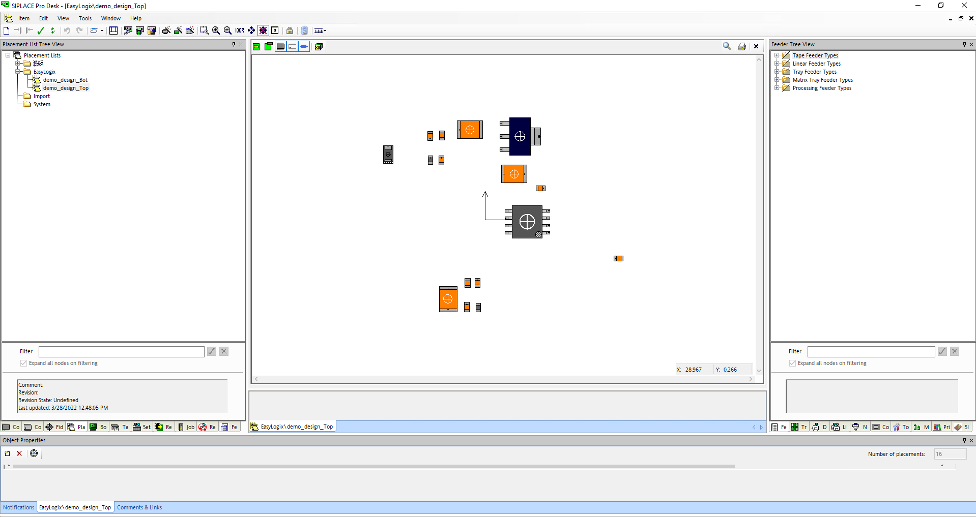
When clicking the 'Create Placement List via OIB' button (7), you are asked to select a folder on the OIB server and enter the name for the placement list(s) for top and/or bottom side. Afterwards, the placement lists are created via OIB. Missing parts, that where not found during the matching process, are automatically created in the 'Component User Path' (see 'OIB Server Manager'). Those created parts are dummy parts without any real outlines or pin definitions. Their information must be completed by the user in the SIPLACE Software afterwards. Components that have the ".comp_ignore" attribute are marked as 'omitted' in the placement list.
Here is a screenshot of the result in the SIPLACE Software: