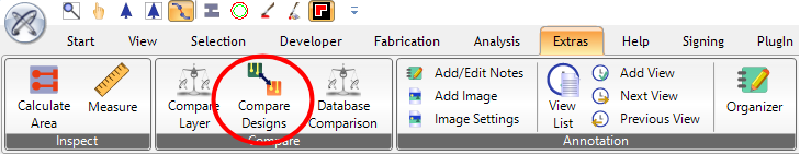
To compare graphically, you can either start "Compare Designs" via PCB-Investigator or you can start it as a Desktop-App, called "PCB-Investigator-Graphic-Board Compare".

Starting "Compare Designs" or "Graphic-Board-Design", it will result in the same dialog. After the tool has been started, it will look like this.
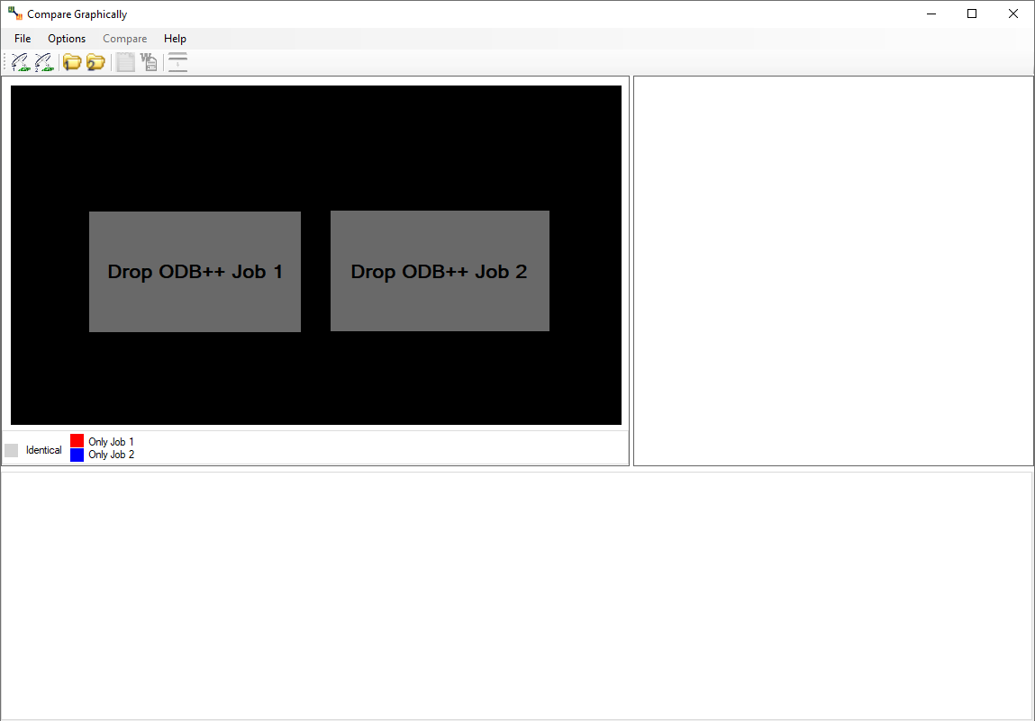
To compare two jobs, you have to add to new designs.
The two currently selected designs are mapped to colors.
![]()
After choosing the second design, the following dialog will open automatically.

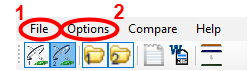
(You can also open this dialog by clicking this button or using the "Compare" tab.)


The first opened dialog will change and will now look like the following picture (only if there are results).
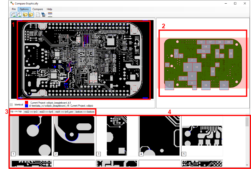
To simplify the dialog, it can be splitted into four different views.
The following GIF´s show what the four areas can be used for.
View 1 + 2:Â

View 3 + 1:

View 4 + 2 + 1:

Â
Further details:
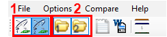
1. Using the "File" tab, you can create different reports of the comparison. The following report formats are available.
The HTML Report may be the best report for visualization reasons. The report looks like this:

2. The "Options" tab allows the following opportunities.

1. The "Tolerance" option allows you to adjust the difference the PCB elements of the two layers may have. (Smaller values cause a higher computing time.)
2. The second option "Show PCB-Investigator" opens two instances of PCB-Investigator. Each instance uses one of the chosen designs. Position it side by side to compare it directly. Using the tiles of the main window, the two instances will also zoom in the chosen tile.
3. The option "Activate Layers" and "Deactivate Other Layers" are just influencing the second option "Show PCB-Investigator". Activating them will cause to have a difference in the seperated two PCB-Investigator instances.
Command Line Arguments (Avalable with Version 16 or beta V 15.1):
first and second arguments have to be pathes to the compare designs
-in_profile_only=true
-export_report_path=D:\\output\\example.html
-check_all_layers=true
Example call as batch file:
D:\tmp\PCB-Investigator-Beta\GraphicBoardCompare.exe D:\Data\compare\job1 D:\Data\compare\job2 -in_profile_only=true -check_all_layers=true -export_report_path=D:\tmp\compare.html
Sync Actions

Image Compare - Specific Settings

General
Advanced
List Compare - Specific Settings

Diff Tool Settings
External Diff Tool
Note(!): To provide the program with the list view data, two temporary csv files are created. The paths to these files are appended as arguments to the program call. Only programs which support csv files, which allow command line parameters and which do not require a special syntax to define the files to be compared (eg. like a prefix before the filepath), are supported.
Instance Snchronization - Illustration
If you want to use the synchronization functionality, the new instance of PCB-I must be opened with the button 'Open new instance'

To activate the synchronization functionality, you must click the 'Sync On/Off' button on all instances you want to synchronize.
A green label (with white text) appears in the upper left corner of the main viewport. It shows the process ID under which the PCB-I instances run. The window called MAIN is the root instance. When it is closed, all other windows are closed too and the process is terminated. All windows called CHILD can be safely closed without closing other windows. There is no influence on the synchronization functionality, whether the window is MAIN or CHILD.
Once the windows are synchronized, all functionality and actions set in the Sync/Compare Settings are synchronized between all instances.
To activate the synchronization functionality, you must click the 'Compare On/Off' button on two instances you want to compare.
This also activates the live synchronization for both windows, if it was not turned on before. If the compare is active, all differences between the two opened designs are marked with white lines. The algorithm groups areas with many small changes to a larger area. The exact compare behaviour can be fine-tuned in the Sync/Compare Settings.

If the synchronization is active and any list view is opened in both instances, differences are marked in different colors (List Compare). A round button in the bottom right corner of the list shows that the compare is active. List views of which the button is showing the same number are compared. List views with compare active are also synchronized (sorting, scrolling, filter). Rows with red coloured cells are available in both lists but differ from each other. Green coloured rows and gray coloured columns are only available in one list. To identify rows that belong together, the most meaningful column for each list is used.
By clicking on the round button, a menu can be opened. There you can switch the things that should be synced on and off individually. The blue button in the menu opens an external diff tool. It uses the diff tool set in the Sync/Compare Settings. You don't need to install a separate diff tool for this. By default, one integrated in the PCBI is opened.

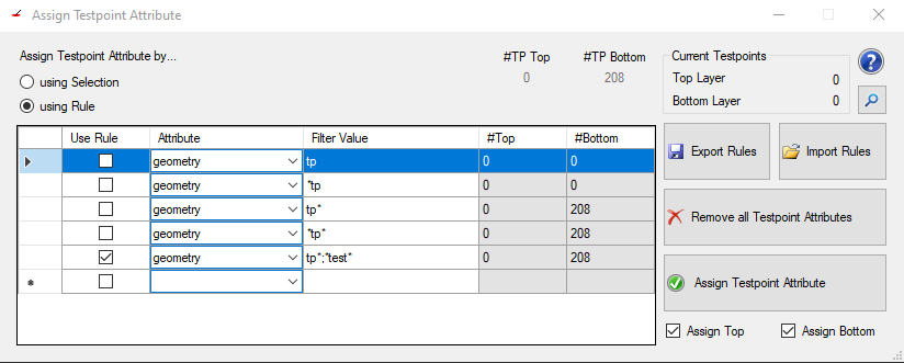
You can find the Testpoint Assign Tool under Plugin >> Assign Testpoint Attribute.
This tool helps to find and mark testpoints in a layout which could be defined via multiple non standardized attributes. Marking them with this tool then helps to standardize this and prepare the layout for following tools (for example the DFT Preperation).
On the top left you can switch between using the current selection or a set rule to find the testpoints and assign the test_point value.
When choosing rules you can add another rule by checking the checkbox of the lowest row in the current listview and then fill out which attribute should be tested and what value needs to be set in said attribute.
All attributes are listed in a simple drop down menu. The Filter Value then has to represent the value of the attribute. Wildcards are allowed when searching for attribute values. The image shows for example all ways to search for "tp" in the "geometry" attribute:
Also it is possible to search for multiple values of the same attribute as shown in the last row. Simply seperate the values with a semicolon.
Boolean attributes do not need any value since their existance already means they are set.
To remove a rule simply select the whole row by clicking on the left most column of the row you want to delete (left of Use Rule) and press the "delete" key on your keyboard.
Checking a rule will select all found possible testpoints of the job (the checkboxes Assign Top and Assign Bottom change the selection depending on the check state of them)
On the top right side there is an information panel showing:
Export Rules exports the currently set rules to a xml file on selected location on the machine or in a cloud
Import Rules imports rules from a file either from the machine or from a cloud
Remove all Testpoint Attributes removes the "test_point" attribute from all pads of the job
Assign Testpoint Attribute adds the "test_point" attribute to either the currently selected pads or the pads found by the selected rule (handled by the radiobuttons "using Selction" and "using Rule")
Assign Top is a checkbox that when unchecked the "test_point" attribute will not be set for the pads on the top layer
Assign Bottom is a checkbox that when unchecked the "test_point" attribute will not be set for the pads on the bottom layer
To find possible testpoints the attribute histogram is a good way to start.
To compare testpoints on both designs, there are several settings you should consider. At the top, there is an option tab. The comparison will just check the position, the diameter and the net, any other attribute will be ignored.
After checking the important attributes, the comparison can be started. Click the "Compare Testpoints" button to start the process.
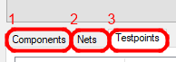
You have many options to define the testpoints:
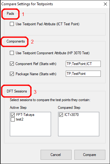
After pad attributes (1), there are different options to find component testpoints (2) and in the third block you can select existing DFT sessions (3) for testpoint definitions.
The results will be shown after the waiting dialog is shut down. Before checking the results, it is necessary to know in what state the result may be.
Possible result states are:

As you can see, this overview is also available in the dialog. It shows you the summary of all results. There is also a checkbox which can be used to list only results with a different state.
Result state definition:
The results which will be shown may look like the following picture.

The different colors show the result status. Clicking one result entry will show you the details below. For example:
Clicking the "different!" state result, the detail view may look like this.
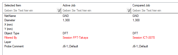
The red colored attributes show you the differences between testpoints of the designs. Black colored attributes are identical. The red and black color depends on the state of the result.
Watch our PCB-Investigator - Graphic Board Compare Video here:
Tutorial: Graphic Board Compare:
Watch our PCB-Investigator - Database Compare Video here:
Tutorial: Database Compare:
Watch our PCB-Investigator - Instance Sync Compare Videos here:
Tutorial: Instance Sync (CAD data)
Tutorial: Instance Sync (PDF document)
Use The Find Dialog or Search Textbox to get a overview with all found Components, nets and properties:


If you use the space key, the quick search appears and you can use some chars to filter the search results:
> search for attributes and properties on copper and other ODB objects
! search for components e.g. type the reference or a part of the reference
? search for attributes e.g. the mount type
$ serach for layer names, you can activate them or deacitvate it without scrolling in the layerlist
% serach for nets, use net name or part of them to find the relevant net and select/highlight them
Note: Quick search is available in V17 and preview beta version! This feature replace the old metro style menu and is available by pressing the space key on the keyboard.
In the search manager it is possible to define different search types, it is possible to add your own plugins with individual searches to the Search Provider List.
Default there is a web serach, a part search and a package search. In each of them it is possible to add additional serach properties to e.g. search in a different library or serach for customize properties.

The Search for... Context menu is on many places available (nearly each list view supports the serach), you can directly start e.g. a bing serach without copy the property or check for existing MPN on your favorite website.
For more information how to customize the search contact support@easylogix.de